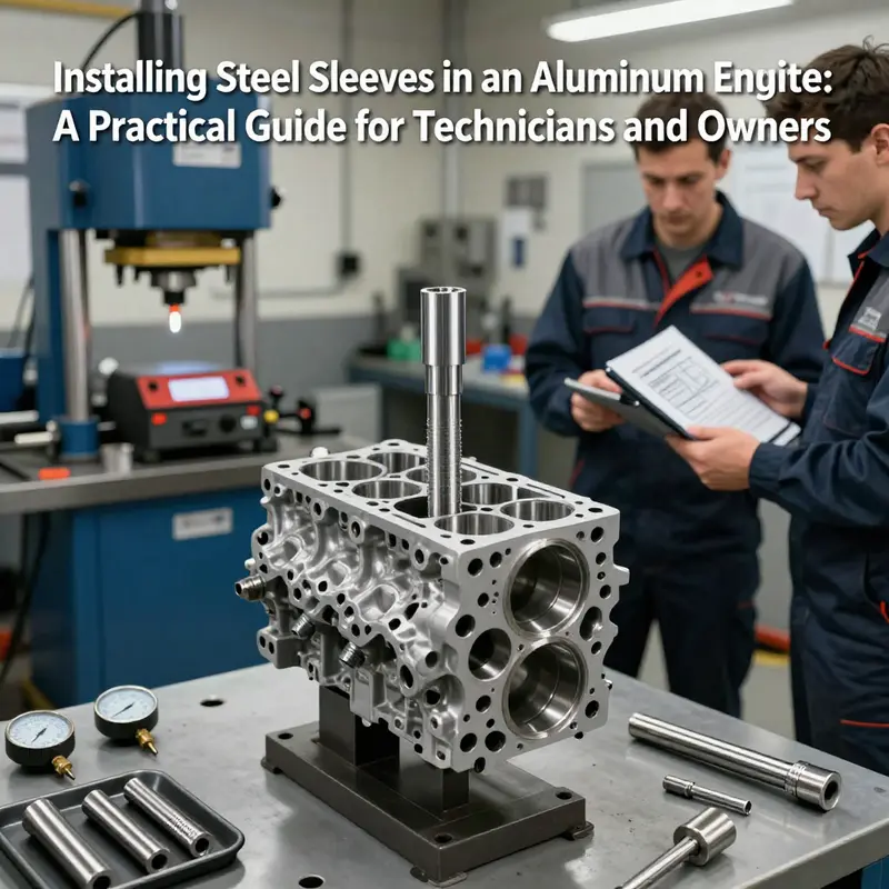
Aluminum engine blocks offer weight savings and thermal advantages but can suffer cylinder wear, damage, or the need for performance-oriented reinforcement. Installing steel sleeves in an aluminum engine restores bore integrity and can extend service life or enable larger displacement upgrades. This guide explains the full process from precision block preparation to final assembly, focusing on practical details motorcycle owners, auto owners, parts distributors and repair shops need to plan, quote, or perform the work. Chapter 1 covers block inspection, alignment and thermal considerations before any cutting begins. Chapter 2 explains sleeve types, material choices and the machining tolerances required for a correct press or shrink fit. Chapter 3 describes the primary installation methodologies — interference (press), shrink-fit, and wet-liner approaches — and practical jigs, fixturing and risk controls. Chapter 4 details the finishing operations: deck alignment, bore honing, ring fitment checks and reassembly best practices. Follow these steps to make informed decisions, communicate requirements to machine shops, and reduce the risk of installation errors that lead to premature failure.
null
null
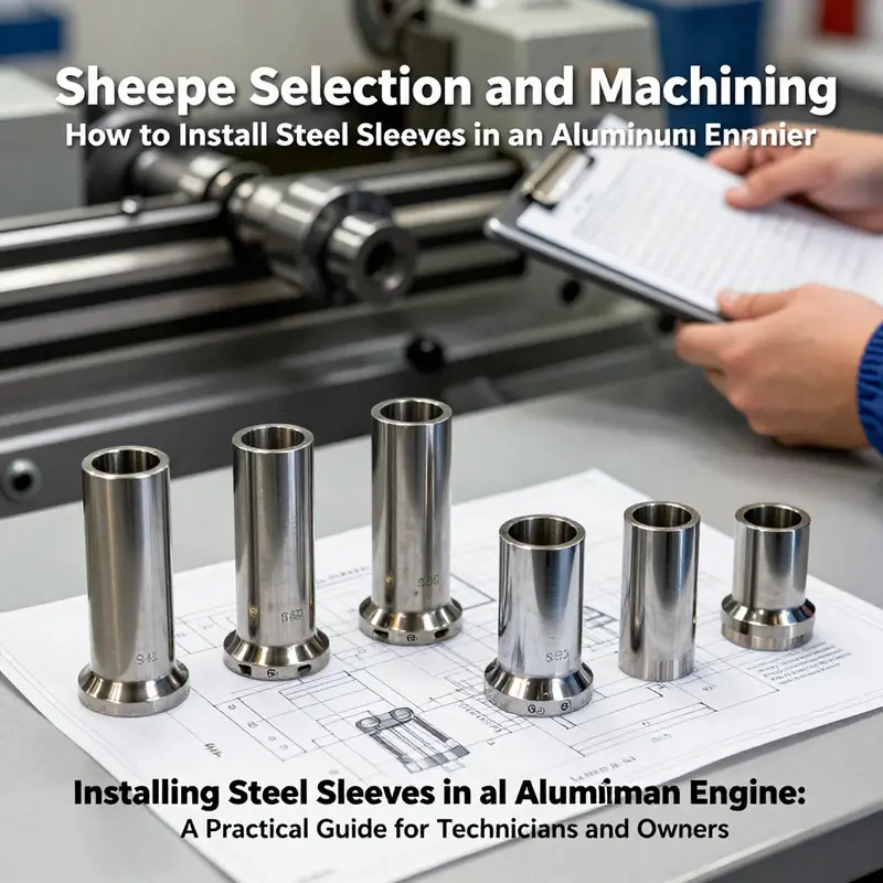
The Tight Fit: Sleeve Selection and Machining When Installing Steel Sleeves in Aluminum Engines
In the realm of engine rebuilding, there are moments when standard practice gives way to precision engineering. Aluminum blocks, prized for their lightness and strength, often arrive in the workshop with boosted performance targets or bore wear that ordinary repair methods cannot adequately address. In these moments, technicians may consider installing steel sleeves to restore cylinder integrity and improve durability. It is not a routine maintenance task; it is a specialized process that sits at the intersection of metallurgy, precision machining, and thermal engineering. For readers new to the concept, a good starting point is to understand what an engine sleeve is and why sleeves might be selected for an aluminum block. A concise overview can be found in resources that define engine sleeves and their purpose—it helps frame the discussion that follows. What are engine sleeves. This chapter builds on that foundation, but it also dives into the decisions and machining reality that underlie a successful installation.
When a bore is damaged or when a performance target demands more consistent ring seal and wear resistance, steel sleeves offer material properties that aluminum alone cannot provide. Steel provides hardness, surface resilience, and a well-established wear profile that helps resist the repeated contact stresses of piston movement. Yet introducing steel into an aluminum block is not a straightforward matter. The two metals speak very different mechanical languages when heated and cooled. Aluminum expands more with rising temperature than steel does, and that difference governs every design choice from the initial bore preparation to final seating and finishing. The objective is not simply to press a sleeve into a hole; it is to create a functional, thermally compatible assembly where the sleeve remains firmly seated, maintains concentricity, and preserves a precise surface finish that allows the piston rings to seal efficiently throughout the engine’s life. The process hinges on a carefully engineered interference fit—the sleeve must grip the bore tightly enough to resist movement under hot operating conditions, while the surrounding aluminum must not crack, warp, or creep in ways that undermine that fit. This balancing act defines the core of sleeve selection and machining.
A practical starting point is material pairing and fit. The sleeve material, typically steel, must align with the engine’s performance expectations and duty cycle. The bore in the aluminum block is then prepared to receive a sleeve whose outer diameter is slightly larger than that bore—an interference fit. Achieving the right amount of interference is a nuanced task. It must accommodate thermal expansion during warm-up, while remaining stable at peak temperatures. The tolerances must be tight enough to prevent smear, misalignment, or a restrictive seal that would degrade compression, but not so tight that the aluminum yields prematurely or the sleeve binds. These tolerances are not guesswork; they are grounded in experience, material data, and, increasingly, metrology-enabled machining that can verify concentricity and fit in real time as the sleeve goes in. A well-designed interference fit helps distribute stresses evenly and reduces the chance of localized hot spots that could lead to premature wear or block distortion.
In the context of dry sleeves—where the sleeve does not share a direct coolant path with the combustion chamber—the heat transfer challenge becomes even more pronounced. The thermal path from combustion heat to the cooling system routes primarily through the aluminum block, not through the sleeve itself. That means the block-sleeve interface must be exceptionally robust, and the sleeve’s external surface must be prepared to bare heat transmission in a controlled way. Dry sleeves enable lighter, more compact engine designs, but they demand exceptional precision in both machining and assembly. Any gap or misalignment can become a hot spot, inviting distortion or accelerated wear. Consequently, the machining tolerances in the bore and the sleeve’s outer diameter are not mere numbers; they are a carefully engineered envelope that governs heat flow and structural stability. Real-time measurement during production—whether with high-precision dial indicators, bore gauges, or more advanced metrology rigs—becomes a standard component of the process. The goal is a uniformly tight fit that resists creep as temperatures swing from cold start to full operating heat, while ensuring the sleeve remains centered relative to the piston axis.
To achieve that level of precision, several tooling and surface preparation considerations come into play. The bore in the aluminum must be prepared with care, using tools and finishes that leave a clean, true surface ready to receive the sleeve. The outer diameter of the steel sleeve often requires finishing operations to ensure a uniform press fit. Depending on the sleeve treatment, there may be an additional surface layer—such as nickel plating or nitriding—that reduces friction, improves wear resistance, and mitigates galling during the initial cold seating and the first handful of heat cycles. Surface finishing is not cosmetic; it is functional. A smooth, uniform surface helps the sleeve seat evenly and reduces the risk of micro-motions at the metal interface, which could become a cradle for wear particles and seal degradation in service.
The final surface interaction after installation is a topic that professionals treat with particular seriousness. Once the sleeve is pressed or otherwise seated, the bore must be honed to the sleeve’s outer diameter with a finish appropriate for the intended piston rings and the engine’s intended RPM range. Honing is more than cleaning up a diameter; it is about achieving a surface texture that supports consistent oil film behavior, contributes to ring seal stability, and sustains crosshatch patterns that encourage even wear and reliable sealing under thermal duress. The overall surface finish on the sleeve and the bore, along with the sleeve’s internal geometry and any coatings, interact with the piston rings to establish how well the engine can seal and how quickly it can settle into uniform operation after assembly.
Surface treatment choices for steel sleeves—such as plating or nitriding—tend to be leveraged to improve initial run-in behavior and long-term wear characteristics. These choices are not optional glamour; they influence friction coefficients, wear resistance, and even the durability of the interface during the critical first hours of operation. The practical outcome is that a sleeve’s service life depends not only on the sleeve’s base material but also on the quality of the finish and the integrity of the bond between sleeve and block. The interplay of the surface treatment with exhaust heat, combustion byproducts, and lubricating film is a factor engineers weigh as part of a broader reliability strategy. In a well-executed installation, these decisions are aligned with the engine’s operating envelope and with the block’s metallurgical characteristics so that the cooled region becomes a stable home for the bore and ring pack rather than a source of failure.
The role of standards and guidance should not be understated. The automotive and engineering communities have long recognized the complexity involved in cylinder liner installation, especially when steel sleeves are used in aluminum blocks. Contemporary guidance, including SAE publications, provides the framework for tolerances, material pairing, interference-fit guidance, and quality-control practices that help prevent premature failures. The SAE J2469 publication, Engine Block Design and Cylinder Liner Installation Practices, is frequently cited as a benchmark reference. It covers lubrication considerations, thermal compensation strategies, and the importance of achieving a consistent, validated fit during machining and assembly. While a shop may tailor procedures to a given engine family, these guidelines offer a language and a set of expectations that help teams communicate, validate, and verify the critical dimensions and interfaces involved in a sleeve installation. The practical takeaway is that successful sleeve work hinges on combining rigorous metrology, disciplined machining, and validated material treatments into a coherent process that can be repeated reliably across builds.
From the perspective of engineers and machinists, sleeve installation is a multi-disciplinary exercise. It demands a precise understanding of how materials behave under heat, how an aluminum block will respond to the mechanical stress of a tight interference fit, and how to preserve the block’s overall structural integrity while delivering the bore quality that a modern engine requires. In practice, technicians plan the project with an explicit tolerance strategy, a clear plan for bore preparation, an exacting approach to sleeve handling and seating, and a reminder that the work must be verified with thorough measurement and, ideally, post-install inspection to confirm concentricity and surface finish across the final bore. The end result—a properly sized, uniformly finished bore with a steel sleeve seated securely within an aluminum block—conveys not only the state of the machine shop’s equipment but also the fidelity of the design intent. It is a tangible demonstration that the engineer’s concept of a composite, heat-tolerant interface has been realized in metal and that the engine has a robust platform for the next hundred thousand miles or more.
This topic naturally leads back to the broader context of engine restoration and performance work. In many projects, the sleeve option is weighed against other strategies such as honing and re-plating, or even selecting a block with an inherently more compatible sleeve design. The choice depends on a constellation of factors: the engine family, the block’s original design and its current condition, the desired compression profile, the operating environment, and the availability of skilled machinists and precise equipment. For educators and practitioners, the essential message is that sleeves in aluminum blocks are not a panacea; they are a carefully engineered decision that should be executed with an awareness of thermal management, structural limits, and long-term reliability. The resulting assembly, when done properly, can deliver improved wear resistance and piston-ring seal performance, albeit at the cost of increased process complexity and the need for specialized tooling and metrology. As with all advanced engine work, ongoing research, validated data, and adherence to established principles help ensure that the final product remains both safe and capable, ready to perform in the demanding conditions for which modern engines are designed.
In the end, sleeve selection and machining are not merely about fitting a sleeve into a hole. They are about designing an interface that respects the physics of two metals with divergent properties, orchestrating a controlled press fit, and finishing the assembly with a surface treatment and honing regime that sustain performance under real-world duty. The chapter’s exploration of these ideas aims to illuminate the careful balance between theory and practice that underpins any successful installation. For ongoing learning and deeper technical grounding, consult the broader literature and professional references, which provide tolerancing charts, interference-fit ranges, and machining sequences that professionals use to translate design intent into a dependable engine component. And as the field evolves, the core principle remains: the sleeve must become a durable, thermally compatible part of the block, not a passive insertion. It must work in harmony with the rest of the engine, from the crank to the cam to the lubrication network, so that the entire assembly behaves like a single, well-integrated system. For readers curious about the broader implications of sleeves within engine architecture, the discussion above connects the practical realities with the standards that guide them, while the next section of the article will continue exploring related topics in engine reliability and performance.
External resource: For formal guidance and deeper standards, see SAE J2469—Engine Block Design and Cylinder Liner Installation Practices. https://www.sae.org/publications/technical-papers/content/2021-01-0187
Joining Hardness with Lightness: Precision Methodologies for Installing Steel Sleeves in Aluminum Engine Blocks

In the world of high-performance engines, the boundary between materials often comes under stress. Aluminum blocks promise lightness and heat management, yet their bore integrity can demand more than a simple repair patch. The concept of inserting a steel sleeve into an aluminum engine is not a routine maintenance task. It sits at the intersection of precision machining, advanced metallurgy, and highly controlled manufacturing processes. To many readers, the idea may sound like a mashup of two different worlds, but when engineered correctly it can restore bore integrity, enable higher load capabilities, and extend engine life in demanding applications. The narrative here is not about a casual swap of parts; it is about understanding the conditions under which a sleeve can be a viable reinforcement and about the meticulous sequence that makes such a joint reliable rather than brittle.
At its core, sleeving an aluminum block with steel is about bridging two dissimilar materials. Aluminum, with its low density and high thermal conductivity, behaves very differently from steel, which supplies strength, wear resistance, and a different coefficient of thermal expansion. The cylinder bore is not just a smooth surface for the piston; it is the stage where heat, pressure, lubrication, and motion converge. When a bore sustains damage or when a rebuild aims to raise the engine’s life and performance, a steel sleeve can provide a robust inner surface that resists wear and tolerates higher cylinder pressures. But such an intervention requires more than a press fit or a quick repair technique. It demands precision bore preparation, accurate sleeve sizing, and a controlled assembly that accounts for thermal and mechanical stresses that will unfold during engine operation.
The procedure can be imagined as a careful three-act performance, each act building on the accuracy of the previous one. The first act, positioning, is where the sleeve is coaxed into a precise relationship with the aluminum bore. The centerline of the sleeve must align perfectly with the piston axis, and the bore must be prepared to an exact diameter and surface finish. This is not a task for the casual garage; it requires dedicated machining, alignment checks, and often a specialized hydraulic setup to avoid forcing the sleeve out of true alignment. The second act, gap adjustment, handles the realities of dissimilar materials under thermal cycling. Aluminum expands and contracts differently than steel. If the sleeve sits too tightly, stress concentrations can arise; if too loose, shear or micro-movement can undermine sealing and stability. The goal is an interference fit that remains stable across temperatures and operating conditions, with just enough clearance to permit a uniform seal and smooth piston ring contact. The third act, bolt fastening or mechanical interlocking, locks the sleeve into place with a retention method that prevents radial migration while distributing loads evenly across the joint. The fastening approach must not introduce distortion or introduce stamping-induced microcracks in the bore. Collectively, these steps constitute a disciplined sequence in which precision and restraint trump speed.
The practical steps to achieve this are exacting. The cylinder bore is first machined to the target diameter that will accommodate the chosen sleeve. The bore finish must be within the tight tolerances specified by the sleeve manufacturer and the engine’s own design limits. The sleeve itself is selected based on the engine’s bore dimensions, the intended operating conditions, and the mechanical requirements of the cylinder surface. In some cases, the sleeve is cold-pressed or press-fit into the bore, while in others a heated aluminum block is used to facilitate insertion and reduce the risk of local deformation. A hydraulic press or a controlled cold-hammer approach may be employed to seat the sleeve squarely, with checks for concentricity and parallelism again central to success. Once seated, the outer surface of the sleeve may require careful finishing, including honing to the correct surface finish and diameter to ensure a proper piston ring seal. This honing step must guarantee the sleeve’s inner bore is perfectly round and has the right roughness profile to support uniform ring seating and lubrication flow.
What often escapes casual discussion is the subtle, sometimes decisive, influence of interfacial chemistry. When steel meets aluminum, a thin, brittle layer of intermetallic compounds (IMCs) can form at the Al–Fe interface. The literature on dissimilar Al–Fe joints emphasizes phases such as AlFe and AlFe3, along with more complex configurations like Al2Fe and Al5Fe2, whose presence and morphology depend on processing history. In the context of additive manufacturing, rapid diffusion and non-equilibrium cooling can create IMC layers with a spectrum of ductility and brittleness. The right processing window aims to favor ductile IMCs that can distribute stress without propagating cracks. This is not merely an academic concern; it directly affects fatigue resistance, crack propagation paths, and the long-term integrity of a sleeved joint. The modern twist in this field comes from leveraging machine learning and first-principles calculations to predict which IMC configurations are likely to form under specific heat and cooling regimes. By forecasting phase formation, engineers can adjust laser parameters, heat input, and cooling rates to tilt the microstructure toward more robust, less brittle interfaces. The optimization is subtle but consequential, and it illustrates how high-performance engineering blends materials science with data-driven insight.
The aerospace literature offers a compelling parallel. In aerospace, the promise of additive manufacturing and intricate sleeve geometries hints at weight reduction, improved cooling, and finely tuned load paths. The ability to produce complex sleeve shapes that fit into tight tolerances can support more efficient thermal management in high-demand components such as turbine sections or airframe-integrated cooling passages. Yet, the same body of work warns that achieving high ductility in the as-built state remains a challenge. Equally instructive is the study of equiaxial and textured structures in other alloys, including titanium, which provides analogies for how different crystal morphologies influence interface strength and fatigue behavior. Taken together, these insights emphasize a central truth: the success of a steel sleeve in an aluminum engine is not just about the sleeve itself but about the entire thermomechanical ecosystem that surrounds it—from the moment the bore is bored to the final engine assembly and beyond into service.
An important nuance is the method of attachment and the form of mechanical retention. Depending on the design, sleeves may be bolted or interlocked into the block. Bolted assemblies require careful torque control and sometimes the incorporation of dowel features or other alignment aids to maintain concentricity under service loads. Interlocking approaches might involve surface texturing or mechanical undercuts that lock the sleeve in place as the block is clamped during assembly. Both approaches must consider potential relaxation under heat and pressure, which can alter clearance and seal integrity. The selection between bolted and interlocked schemes is not a casual choice; it is a reflection of the engine’s anticipated duty cycle, the lubrication regime, and the manufacturing tolerances that the shop can reliably maintain.
For the reader seeking practical familiarity within a broader automotive context, a useful touchstone is the idea that engine sleeves, in general, can be part of a broader strategy to address bore damage rather than a routine feature of every aluminum block. The distinction matters. In everyday repair, the general response is to replace worn rings or to rebuild with standard liners in engines designed for that path. When the design calls for sleeves in aluminum, though, the choice is typically driven by performance goals, bore integrity restoration, or the desire to sustain higher compression and stress without sacrificing aluminum’s thermal advantages. In such cases, the sleeve becomes a bridge across material systems, but only if the alignment, gap, and bonding processes are executed in a controlled, measurement-driven manner.
This discussion would be incomplete without acknowledging the broader ecosystem that supports such specialized work. Official service manuals and reputable engineering references provide the tested procedures and tolerances that underwrite safe operation. Within the community of engine builders, there is a shared recognition that this is not a do-it-yourself task to be tackled on a whim. It is the sort of undertaking that benefits from access to a machine shop with precise boring capabilities, alignment fixtures, calibrated torque tools, and surface finishing equipment. The finishing touches matter: the honing of the final bore, the inspection of concentricity, and the verification of the sleeve’s seating. Each step contributes to the ultimate question of whether the sleeve will deliver consistent compression, reliable lubrication, and robust resistance to thermal cycling over the engine’s life.
For readers exploring related questions in a concrete vehicle context, a relevant internal resource discusses common queries about sleeving in engines and how to approach these decisions. For example, a discussion on whether certain models with aluminum blocks can be sleeved provides practical context and reflects the broader industry practice that sleeves are typically reserved for specific rebuilds or performance upgrades rather than routine maintenance. The linked article delves into general considerations about sleeves and aligns with the sentiment that such work is a highly specialized service.
In closing, the possibility of installing steel sleeves in an aluminum engine block rests on a tripod of precision machining, thoughtful materials integration, and disciplined assembly. The three-stage process of positioning, gap adjustment, and fastening interlocks with thermomechanical realities—the different expansions, the interface chemistry, and the long-term fatigue behavior. The modern twist comes from the ability to anticipate and steer microstructural outcomes through processing choices, aided by computational prediction and experimental validation. The result, when done correctly, is a joint that respects the benefits of aluminum’s lightness while delivering the durability and wear resistance of steel at the cylinder surface. It remains, however, a specialized craft requiring skill, tools, and a rigorous quality-control mindset. For designers and engineers, the takeaway is clear: if a sleeve is contemplated, it should be approached with a system-level view that accounts for the full spectrum from bore preparation to final assembly and service life. The payoff is not just restoring an engine; it is extending the possibilities of how aluminum and steel can work together in high-performance propulsion.
For readers seeking a concise, domain-relevant perspective on current research trends that underpin these practices, the following external resource provides a rigorous exploration of equilibrium and non-equilibrium metallurgical phase formation in dissimilar aluminum–steel joints. It highlights how both experimental and computational methods illuminate the pathways by which interfacial phases form, and how future process optimization might steer these pathways toward more robust and reliable sleeves in aluminum engines. https://www.nature.com/articles/s41598-021-97755-3
Internal reference for practical context can be found in related discussions on sleeving strategies for aluminum-block engines, such as the article that investigates whether certain aluminum engines are sleeved. For readers who wish to locate a concise articulation of this topic within a real-world maintenance context, see Are Toyota Aluminum Engines Sleeved?. This link offers a focused look at sleeve concepts and their applicability to aluminum engine designs, reinforcing the notion that sleeves are a specialized option rather than a universal solution. The discussion there dovetails with the nuanced engineering perspectives presented here, emphasizing the careful judgment required when considering sleeves as part of a rebuilding or performance strategy.
Finish, Fit, and Fusion: Final Machining and Assembly When Sleeving an Aluminum Engine Block
The final machining and assembly phase of installing steel sleeves in an aluminum engine block is where theory meets practice in a hard-edged, measurable way. It is the stage where all prior preparation—the careful bore sizing, sleeve selection, and alignment work—converges into a precise, repeatable fit. The goal is not merely to insert a steel tube into an aluminum hole, but to create a stable, concentric, low-leakage interface that preserves the block’s geometry through every heat cycle, seizure risk, and piston stroke. In this part of the process, the engineer’s respect for tolerances becomes the engine’s lifeblood. When done correctly, the assembly will deliver consistent compression, reliable oil control, and long-term durability. When done carelessly, even the best sleeve material and bore geometry can fail under the first handful of heat cycles. This is why the final machining and assembly steps demand disciplined measurement, controlled heat or cooling strategies, and a rigorously defined seating depth that harmonizes with the block deck, the sleeve shoulder, and the piston travel. It is a choreography that rewards patience and precision, and it tests the limits of even experienced machine shops.
From the outset of final machining, the geometry of the bore and the sleeve must be treated as a single system. The bore in the aluminum block must be concentric with the engine’s main bearing axis and round along the entire length where the sleeve will reside. Any ovality, taper, or misalignment creates a mismatched interface that can seed oil leaks, uneven piston ring seal, or a distorted combustion chamber. The inner diameter of the sleeve, while dictated by the chosen wall thickness and outer diameter tolerance, must be honed or finished to an exact size that yields the designed interference fit without introducing radial stress concentrations. In practice, this means a measured, repeatable approach: first, verify the hole is within flat, true reference surfaces; second, control bore finish to a light, uniform texture that can accept the sleeve’s outer surface; and third, confirm that the sleeve’s outer diameter is within the anticipated press-fit window around the entire circumference. The mathematics of the fit are not exotic, but the execution is exacting. Too little interference invites movement over countless heat cycles; too much interference risks distorting the bore or cracking the block. Every tenth of a thousandth of an inch matters when the goal is a long-lived seal between dissimilar metals.
A key design feature often encountered in steel sleeves for aluminum blocks is a bottom shoulder or stepped seating surface. This shoulder is not cosmetic: it locates the sleeve axially and resists migration during operation. In practice, the shoulder ensures that the sleeve cannot drift under pressure from cylinder head torques, and that the piston rings align with the bore in a predictable way. The shoulder also sets the sleeve’s seating depth relative to the deck surface, which affects how the piston travels within the bore. During final machining, the machinist must confirm that the sleeve’s outer geometry matches the block’s counterbore geometry and that the shoulder sits flush or slightly proud as the design dictates. If the shoulder is misseated, the interface could leak or creep, nullifying the benefits of the sleeve and allowing oil to bypass or combustion gases to escape.
Thermal management is not an afterthought here. Aluminum expands more than steel when heated, and the engine experiences significant temperature swings in service. The assembly process, therefore, often leverages a thermal differential to aid a smooth, uniform press fit. There are two common approaches: heating the aluminum block (or the region around the bore) so it expands slightly, or cooling the steel sleeve so it contracts. Either method must be controlled and uniform, avoiding localized hotspots that could warp the bore. If heating is used, the sleeve may be preheated minimally enough to maintain dimensional stability while the bore expands just enough to accept the sleeve evenly. If cooling is favored, the sleeve is brought to a temperature where its outer diameter shrinks uniformly, ensuring that it slides into the bore without tilting. In either case, careful timing is essential; once the fit is achieved, the assembly must be allowed to return to ambient conditions with the sleeve fully seated and the interface free of gaps. Surfaces must remain clean and dry during this process to avoid sealants or contaminants altering the interference characteristics.
Surface preparation and the care of lubricants or anti-seize compounds during assembly are nuanced steps that influence long-term performance. The sleeve and bore should be clean of debris and protective coatings that could compromise the interference fit. Depending on the sleeve design and the block material, a light, compatible coating or anti-seize compound may be applied to the sleeve’s outer surface to facilitate seating and to reduce galling during insertion. The key is to use products that are compatible with the engine’s lubrication regime and that do not leave a residue that could interfere with the bore’s final finish or the piston rings’ seating. The choice of lubricant is not about making the install easier; it is about ensuring a stable, repeatable mating surface that does not alter the final dimensions or the friction characteristics of the interface.
When the sleeve is pressed into the bore, the operator must ensure that the seating is square and uniform. A hydraulic press is commonly used for this critical operation, with fixtures designed to keep the sleeve perfectly vertical and coaxial with the bore axis. Any tilt or nonuniform contact can push the outer sleeve surface into the bore unevenly, leaving micro-gaps or inducing a distorted cross-section that undermines ring seal. The process is conducted in stages, with continuous checks for seating depth. The exact depth is a design parameter—whether the sleeve should be flush with the deck, slightly recessed, or slightly protruding above the deck face—and it must be adhered to with precision. After seating, the sleeve must be checked for any evidence of movement. The anti-migration features, if present, should show a clear, even contact with the block’s counterbore shoulder. A misfit here is not just a minor cosmetic issue; it is a fundamental misalignment that can manifest as ring land wear, oil control issues, or even partial bore loss.
Post-installation machining of the inner bore is often necessary to bring the sleeve’s inner surface to the final specification. The bore geometry of the assembled sleeve must be coaxial with the block’s axis and consistent along the full height of the sleeve. In many designs, the inner diameter of the sleeve is first honed or re-bored to the final size after seating. This operation is not a mere touch-up; it is a finish that establishes the exact surface finish, roundness, and straightness required for piston rings to seal properly and for lubrication to be distributed evenly. The challenge is to maintain concentricity between the sleeve’s inner surface and the block’s main bore axis while ensuring the bore remains free of taper and ovality. Any deviation can cause uneven ring gaps, which in turn affects compression and oil control. The finishing step must preserve orientation; thus, fixtures and references used during inner-bore finishing must align with the sleeve’s outer reference surface and the block’s deck interface.
Quality assurance during and after final machining is not a single measurement but a sequence of checks that verify that the sleeve is seated correctly, that the outer diameter remains within the interference fit tolerance around the circumference, and that the finished inner bore meets the target size and roughness. Roundness gauges, bore indicators, and dial indicators are used to map cross-sections along the cylinder height. Any observed out-of-roundness or taper triggers a corrective plan, which may include additional honing to the final diameter or re-checking the sleeve seating depth. Surface finish is also critical; the inner bore must have a finish that supports the recommended oil film and ring dynamics for the engine’s lubrication regime. The goal is a consistent, smooth finish that reduces scuffing and ensures stable ring sealing across the engine’s operating spectrum.
Beyond the technical steps, practical considerations shape the feasibility and success of final machining and assembly. Material compatibility remains fundamental: aluminum and steel expand differently, and the assembly must tolerate these changes without loosening or gapping during warm-up and hot operation. The magnitude of the interference fit must be carefully controlled. Too little interference leaves the system vulnerable to movement and leaks; too much can stress the aluminum block or crack it under thermal cycles. Seating depth must be defined with respect to the deck surface and piston travel, so that the rings align with the bore at the expected bottom dead center and top dead center, and so that the compression and oil control strategies remain effective across the engine’s operating range.
Cleanliness, inspection discipline, and a documented verification workflow are not optional extras but essential components of the final assembly. Each stage—bore prep, sleeve seating, post-install bore finishing, and final assembly—should be accompanied by measured data: bore roundness and straightness at several cross-sections; sleeve seating depth; outer diameter and concentricity of the sleeve; inner bore finish and size; and verification that the deck surface remains flat and true relative to the block’s axis. Any deviation should be traceable to a source, whether it is tool wear, misalignment in the press fixture, or contamination at the interface. The end goal is to preserve a stable seal between the piston rings and the sleeve, maintain oil control at both the main gallery and the ring grooves, and ensure that heat transfer is not compromised by surface irregularities at the interface.
A final note on knowledge transfer and ongoing practice: while the overarching principles—precise bore geometry, a reliable interference fit, axial and radial alignment, and careful post-install bore finishing—apply across engines, the specifics always depend on the block design, the sleeve geometry (full-length versus stepped sleeves), and the intended operating duty. For readers seeking a broader understanding of sleeve concepts, a concise overview of engine sleeves can be found in resources like this open reference: What are engine sleeves? This kind of background helps frame the decisions made during final machining and assembly and explains why the measured tolerances and seating depth are not arbitrary but are tied to the block and piston geometry.
If you are working through a project or planning an overhaul, the guidance above is not a substitute for the original service manuals or the engine maker’s specifications. Each engine family may have its own constraints, recommended finishes, and seating depths. When in doubt, consult manufacturer-supported manuals or professional machining references to tailor tolerances and procedures to the exact model you are sleeving. The process described here is designed to illustrate the principles and the disciplined approach required for reliable sleeving in aluminum blocks. It is not a casual, one-size-fits-all procedure, but a careful integration of material science, precision engineering, and meticulous craftsmanship.
For readers who want to explore the broader context of sleeve practices, these discussions can be complemented by observing how sleeve concepts translate across different engine designs and how technicians adapt the same core principles to varying geometries and load profiles. The core idea remains constant: the interface between sleeve and block must behave as a unified, stable system through all operating conditions. Only through rigorous final machining, proper seating, and disciplined inspection can that objective be achieved. External observers who want to deepen their understanding can consult open technical resources that discuss steel sleeve installation in aluminum engine blocks and related finishing and assembly considerations. As with any high-stakes machine work, the path to durability lies in methodical preparation, careful execution, and continuous verification at every stage of the process.
Final thoughts
Installing steel sleeves in an aluminum engine is a precision repair that restores bore geometry and can enable performance upgrades when done correctly. The critical path runs from disciplined block preparation through careful sleeve selection, controlled installation method selection, and exacting final machining and assembly. For motorcycle and auto owners, choosing the right machine shop and understanding these steps protects your investment. For parts distributors and repair shops, documenting sleeve materials, tolerances and the chosen installation method reduces warranty exposure and improves outcomes. When tolerances and thermal behaviors are respected, sleeving provides a durable, serviceable solution for worn or modified aluminum blocks.