Removing sleeves from a Perkins 3-cylinder engine is a precision task that blends meticulous planning, the right tooling, and careful execution. This guide speaks directly to motorcycle owners, auto enthusiasts, parts distributors, and repair shops who may encounter sleeve wear, ring corrosion, or sleeve degradation. It starts with rigorous preparation and safety to prevent burns, contamination, or fluid spills. It then advances through disassembly of the cylinder head and gasket, careful positioning of the crank and pistons, and the implementation of proper sleeve-extraction techniques. Each chapter ties back to the core goal: delivering a clean bore ready for a new liner or re-bore, with thorough inspection and verified reassembly steps. The five chapters build on each other to create a holistic workflow—from setup to post-removal checks—so technicians and experienced hobbyists can approach Perkins sleeve removal with clarity, discipline, and measurable quality.
null
null
Freeing the Sleeves: A Cohesive, Hands-On Path to Cylinder Liner Removal on a Perkins 3-Cylinder Engine
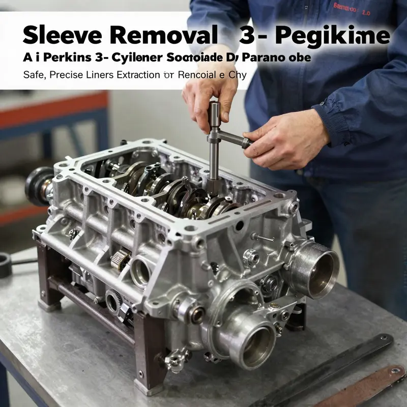
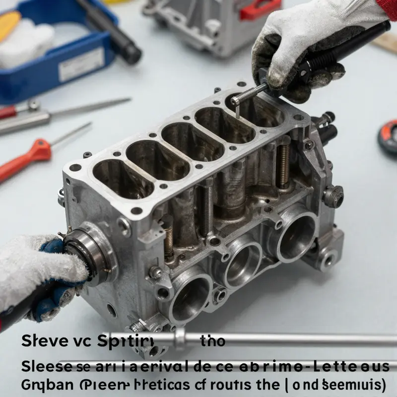
The moment when the sleeves finally loosen their grip is the moment the engine reveals its true condition, and on a Perkins 3-cylinder block that moment must be earned with patience, precision, and a steady hand. Removing cylinder sleeves is not a routine maintenance job you rush through. It demands a measured sequence that preserves the integrity of the block, the seating surface, and the surrounding components. In a Perkins 3-cylinder context, the objective is not merely to extract stubborn liners; it is to do so without introducing waviness, scoring, or misalignment that could jeopardize subsequent reassembly and long-term reliability. The preparation phase sets the tone. The engine must be cold enough to avoid thermal shock, and every fluid in the system should be drained to minimize the risk of spills and contamination. The technician will detach the battery ground first, then isolate electrical circuits, sensors, and fuel lines. Access to the cylinder block requires removal of obstructing items—the air intake system, the exhaust manifold, and ancillary hardware—so that the block presents a clean work surface for the delicate steps ahead. This phase, though routine on many engines, plays a pivotal role in preventing missteps once the work truly begins. A detailed, model-agnostic awareness helps, but the real value comes from aligning every action with the Perkins service manual for your specific variant and serial number. The act of removing the cylinder head follows a disciplined discipline. Bolts are loosened in a crisscross pattern, stepping through the sequence to ease uniform pressure relief and avoid warping. The cylinder head is lifted with care, and the gasket is removed. A quick visual inspection of the head and the seat surfaces is essential; any warping or lingering distortion can translate into a compromised seal on reassembly. When the head is out of the way, the next move is to tackle the oil pan and allied components. The pan is unfastened in a symmetrical pattern, the oil pump detached if necessary, and the drive chain or gear reviewed for any slack or wear. Clearing debris from the lower end of the engine becomes a preventive step that saves time in the long run by avoiding subtle misalignments during reassembly. The crankshaft becomes a focal point as the process advances. With a wrench on the crank pulley bolt, the piston in the cylinder you are exposing is rotated to bottom dead center (BDC). This positioning is not for aesthetics; it is a practical maneuver to minimize interference between the piston and the sleeve during removal. The connecting rod caps and bearings are then carefully loosened and removed for the cylinder of interest. It is crucial to note alignment marks on the rod and cap. A mix of care and memory ensures you return every piece to its original orientation, which matters when you reassemble the engine later. The sleeve itself is the centerpiece of this chapter’s challenge. A proper cylinder liner puller is not optional; it is essential. Hook the puller around the top edge of the sleeve, align it for even load distribution, and begin to tighten the central screw. Gentle, incremental tightening—never a rush—will coax the sleeve out while preserving the bore and the seating surface. If a puller is not available, some practitioners turn to a hydraulic press or a through-bore push with a long steel rod, but these methods carry risk. The temptation to apply a surprising force is strong, yet the risk of cracking the block or deformed liner is real. Heat, used judiciously, can facilitate the process. A warm glow around the sleeve zone—approximately 80 degrees Celsius—softens the metal just enough to reduce friction and ease extraction. The legend of the trade speaks to this technique: controlled heating is a complement to a proper puller, never a brute force substitute. Once the sleeve emerges, the bore must be inspected with a trained eye. Internal features—scoring, taper, corrosion—reveal the engine’s past life and guide whether the block will require honing, sleeve rework, or a block replacement. The measurement of the bore’s diameter, typically via a calibrated bore gauge or internal micrometer, guides decisions about size and tolerances. For a Perkins 3-cylinder engine, typical inspection tolerances require precise adherence: if the bore shows excessive wear or ovality, a sleeve replacement becomes mandatory to restore tight sealing and uniform heat transfer. Keeping the machining surface clean is not merely about aesthetics; it is about preserving the fidelity of the seal for the next sleeve installation. As contamination migrates into the bore, the risk of hot gas leakage, oil burning, or gasket failure grows. With the old liner removed, the bore and the surrounding surfaces receive a careful cleaning using degreaser and controlled air blasts to eradicate debris and residue. A light smear of high-temperature grease on the outside of the new sleeve helps it slide into place with minimal friction. The reinstallation phase—though not the subject of this chapter’s focus—follows its own rigors. The new sleeve, once aligned with the block’s countersunk seating, must be pressed or driven to its correct depth with the right installer tools. The gasket seating surface must be spotless and perfectly flat before the cylinder head is mated again. A note on process fidelity is worth repeating: refer to the Perkins service manual for your precise model, series, and configuration. The procedure you follow for a 3-cylinder variant may show subtle differences from a 4.236 or 4.107 series. Such variations are why the official documentation remains a reliable compass. For those seeking deeper, model-specific insights, this chapter nods to a broader technical thread that explores the exact sequence and tooling for sleeve removal. See the dedicated guide that captures the approach and cautions in a compact, model-focused format: how-to-remove-engine-sleeves. The internal link serves as a practical cross-reference for practitioners who want to cross-check the sleeve-extraction nuances across engine families while maintaining focus on the Perkins 3-cylinder core. The journey from loosened head bolts to a clean bore is a measured evolution. Each step mirrors the careful rhythm of a skilled technician who respects the block’s history and the machine’s future. The process does not end with the sleeve’s removal. Cleaning and preparation for reinstallation are equally critical. A thin film of engine grease on the outer surface of the new sleeve reduces initial resistance during insertion and curtails the first-break-in wear. The seal components—the new gasket, the seating surfaces, and any dedicated anti-leak compounds—must be ready to perform under the higher loads of engine operation after installation. The torque sequence for the head bolts, closely followed in the Perkins manual, ensures the head’s clamping force is uniform. This uniformity prevents temperature-induced distortions and helps maintain a reliable interface between the head and the block throughout service. The final check before the engine breathes again is a manual rotate-and-bleed test. A few manual revolutions by hand verify that the piston gallery and ring gaps do not bind against the new liner. This tactile test captures the feel of a well-executed job and reduces the risk of a startup bind. When the engine finally fires, the first moments after startup are not the moment to discover a misalignment or leakage. The discipline exercised during disassembly—metered removal, careful inspection, and exacting reassembly—translates into long-term reliability and predictable performance. In sum, sleeve removal on a Perkins 3-cylinder engine is a disciplined operation that balances mechanical property with a respect for the engine’s past. The steps outlined here—preparation, head and gasket removal, oil-pan and lowering-gear access, crank-positioning, rod-cap handling, sleeve extraction, bore inspection, and meticulous preparation for reinstallation—form a coherent arc. They are anchored in standard practices and reinforced by model-specific guidance. As with any complex engine task, the challenge and payoff lie in the details—the sequence, the load, the care, and the respect for the component interfaces that keep the machine running cleanly and efficiently. External references can broaden understanding, particularly for the broader cylinder-head and sleeve contexts that share common ground with Perkins engines. A pertinent technical resource from an established supplier catalog highlights compatibility and specification considerations for a related Perkins sleeve and head assembly, offering practical parameters and component matching that readers may find instructive as they prepare for parts selection and fitment. External reference: https://www.alibaba.com/product-detail/Perkins-4-236-4-238-4-cyl-Cylinder_1600584238487.html
Access Granted: Reaching the Sleeve in a Perkins 3-Cylinder Engine Through Oil Pan, Crank, and Piston Positioning
Accessing the cylinder sleeve in a Perkins 3-cylinder engine is a precision task that sits at the heart of any rebuild or sleeve replacement. It is the moment when the engine’s inner geometry becomes exposed and the path to the worn liner is cleared with care. The procedure hinges on a careful sequence that begins with removing the bottom-end barriers—the oil pan—and ends with the piston and crank positioned to give the technician unimpeded access to the sleeve bore. This chapter describes that access phase as a continuous, integrated task, not a litany of disjoint steps. It emphasizes the mindset required: alignment, restraint, and respect for the tolerances that define the engine block’s life. Before you begin any disassembly, you must recognize that the goal is not simply to extract a sleeve but to preserve bore integrity, gasket surfaces, and the crank’s journals so that the engine can live again after the work is done.
The first move in this phase is the straightforward, yet sometimes overlooked, step of draining the engine oil and any residual fluids. The oil pan acts as a bottom reservoir and a non-trivial mass that can become a hazard if left in place during pan removal. Support is the keyword here; an oil pan is neither forgiving nor light when you loosen the last bolts. As you detach the perimeter bolts in a uniform pattern, you maintain a symmetrical gasket surface and prevent warping of the mating surfaces. When the pan comes free, you slowly ease it away to avoid snagging the gasket or dropping oil that could contaminate the crankcase or the floor. Cleaning the mating surfaces is essential, as any leftover sealant or grit can compromise the seal when the pan is reinstalled. A keen eye for debris around the gasket line will save time later, especially if the engine has seen significant use.
With the oil pan removed, you expose the crankshaft, connecting rods, and the lower portions of the cylinder walls. This visibility is not merely mechanical; it is the moment to verify that the path to the sleeve is clear and that no foreign objects lurk in the bore or on the crank. The next move is to position the crank and pistons so that the targeted cylinder’s sleeve can be accessed without interference from the piston crown or skirt. The practical way to achieve this is to rotate the crankshaft by hand using a suitable wrench on the front pulley bolt, watching the piston dome or through the spark plug hole to monitor its travel. Your objective is Bottom Dead Center (BDC) for the piston in the cylinder that will receive the sleeve. BDC is critical because it places the piston skirt furthest from the sleeve wall, providing maximum clearance for the sleeve removal tool to thread into the bore without contacting the piston or rod.
As the crank approaches BDC, a strict discipline must be observed: once the piston sits at its lowest point, the crank must be secured so the engine cannot rotate. A simple wooden wedge between a flywheel tooth and the housing, or a small locking pin placed in the appropriate notch, can hold the crank. This locking is not a mere courtesy; it is the safeguard that prevents the delicate sleeve from being pushed or pressed in a way that might crack the block or misalign the bore. With the crank secured at BDC, you now have a stable platform to insert the sleeve removal tool. The sleeve, usually a press-fit into the bore, requires gentle, even force to emerge. Any attempt to force it with the engine in motion or with uneven pressure risks micro-cracks in the block, nappe distortion, or damage to the thrust surfaces that guide the crank.
The practical mechanics of sleeve extraction rely on a purpose-built puller that can grip the sleeve’s top edge while applying a steady axial pull. The puller should be positioned so its claws seat securely around the top lip of the liner and its central screw aligns with the sleeve axis. As you begin to tighten, slow, measured turns are essential. A little too quickly, and you risk deforming the bore, scarring the cylinder wall, or bending the liner’s outer diameter. The puller’s contact surfaces must be clean to avoid shaving metal or contaminating the bore with dirt. If a dedicated puller is unavailable, two less ideal alternatives exist: a hydraulic press or a through-bore push via a long steel bar. These methods demand extraordinary caution. They can thrust the sleeve out with force, but they also increase the risk of block damage if the sleeve binds or the force is misapplied. In all cases, patient, incremental pressure is the rule and the engine’s internal geometry must be respected.
Removing the sleeve is the culmination of the access phase, but it also signals the moment to examine and prepare for what comes next. A clean workspace and a clean bore are non-negotiable. Any grit in the bore can become a scoring agent the moment the new sleeve is pressed in. After the sleeve clears, inspect the bore for scoring, cracks, or corrosion. The block’s sleeve seat must be free of damage; otherwise, you will have to hone or even replace the block itself. A careful hand with a degreaser and compressed air helps ensure the surface remains pristine for the re-installation of a new sleeve. If the sleeve is to be replaced, the outer surface of the new sleeve may require a light coat of high-temperature grease to ease installation and to prevent the new liner from sticking or seizing as it enters the bore. The goal is a uniform seating that does not require extraordinary force to achieve.
At this point, the chapter’s focus has shifted from the physical act of extraction to the preparation for reinstallation or replacement. The sequence you have followed is not simply about removing a component; it is about managing the delicate relationship between the sleeve, the bore, and the crankcase. If a proper check of the bore reveals damage, consider whether the block must be honed or replaced. If the sleeve is being replaced, ensure that the fit is correct and that the installation tool is aligned with the bore’s axis. The surface finish and the concentricity of the bore are crucial for engine life. It is not enough to slide a new sleeve in place; it must be coaxial with the crank axis and seated evenly to prevent local heat concentrations or uneven wear. In other words, the access phase is the bridge between disassembly and assembly, and any misstep here reverberates through every subsequent phase.
In the broader scope of the project, remember that model-specific specifications—such as torque values, the sequence of fasteners, and the particular type of sleeve for your Perkins 3-cylinder model—vary. The faithful way forward is to consult the Perkins service manual for your exact series and to apply the torque prescriptions and reinstall procedures exactly as written. The manual will also specify the required installer tools or presses, alignment procedures, and any model-specific tolerances that govern how a sleeve should seat. For readers seeking an on-site, practical walk-through that complements this discussion, there is a detailed guide available online that covers the hands-on steps of sleeve removal. It provides a useful companion reference to the concepts outlined here. how-to-remove-engine-sleeves.
As you move from accessing the sleeve to actually extracting and replacing it, the mental posture you bring to the work matters as much as the tools you use. The oil pan’s removal is not just a drain; it is an entry point into the engine’s lower architecture. Positioning the crank at BDC is not merely a mechanical trick; it is an explicit acknowledgment that precision, clearance, and stability govern the operation. A single misstep—an unintended turn of the crank, a misaligned puller, or a rough handling of the piston skirt—can transform a straightforward sleeve swap into a costly repair. The discipline demanded by this phase—careful draining, precise alignment, secure locking, and measured force—reflects the broader truth of engine work: the objective is not to rush but to preserve the engine’s capacity to live again after the repair is done.
When you complete the sleeve removal and the bore inspection, you will be ready to reassemble. The reinstallation sequence follows naturally from the access work: clean all surfaces, inspect the piston and rod positions, install the new sleeve with the correct orientation, and ensure the bore is clean and dry prior to pressing the sleeve in. If a new sleeve requires a press or installer tool, use it according to the manufacturer’s instructions, and verify alignment and seating with a light, coaxial measurement. Finally, once the sleeve is in place, you will reassemble the oil pump, oil pan, and the upper assemblies, re-torquing all fasteners to the specified values. Only after these steps can the engine be tested for compression, coolant integrity, and oil circulation—a test that confirms the sleeve’s integrity and the engine’s readiness to run.
For model-specific guidance and additional safety precautions, always refer to the official Perkins Workshop Manual. It is the definitive source for torque specs, service procedures, and any model-to-model variations that can significantly affect the sleeve removal and installation process. External resources and manuals, when used with careful hands and disciplined procedures, ensure that the work remains within the bounds of safety and reliability that a Perkins engine deserves.
External resource: https://www.perkins.com/support
Sleeve Extraction Mastery for the Perkins 3-Cylinder: A Measured, Tool-Supported Approach to Liner Removal
The sleeve, or cylinder liner, is a quiet powerhouse in an engine block. It supports the piston’s travel, forms the boundary for heat transfer, and endures a daily toll of shock, friction, and thermal cycling. In a Perkins 3-cylinder configuration, removing a sleeve is not a routine maintenance chore but a precise operation that demands respect for the block’s integrity and a clear plan for tool use. This chapter explores a cohesive, methodical approach to sleeve extraction that emphasizes preparation, controlled disassembly, and careful handling of the liner as a component that, once removed, can determine whether a rebuild proceeds on solid footing or stumbles due to hidden damage. The goal is not novelty but reliability: a process that reduces risk, preserves the condition of the block, and lays a foundation for successful reassembly with a new sleeve if required. With the right mindset and the right toolkit, sleeve extraction becomes a disciplined craft rather than a desperate struggle with stubborn metal.
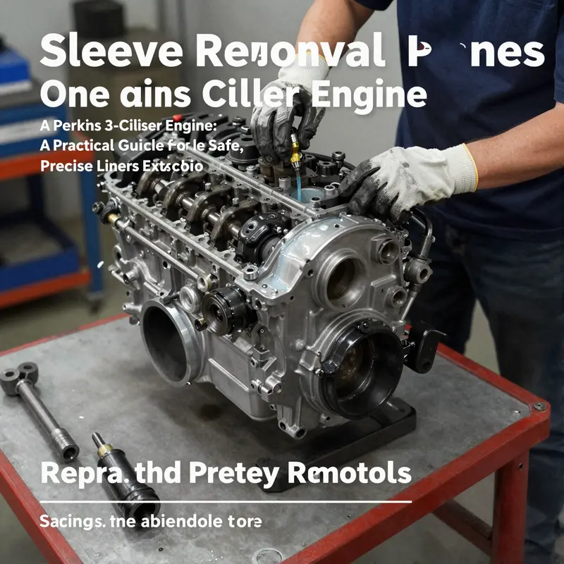
Begin with respect for the engine’s thermal and mechanical history. A cold engine is a safer, more predictable starting point. Standing heat from recent operation can warp metal and obscure measurements. Before touching anything, drain the fluids—engine oil, coolant, and any residual fuel in the system—to minimize the chance of spills and to simplify handling during the disassembly. A careful vacuum or siphon approach is preferable to brute dumping. Disconnect electrical connections—battery ground and all engine-related sensors and injectors—so you won’t inadvertently energize components or damage wiring harnesses during the bench-work. Removing accessories that obstruct access, such as the air intake and exhaust components, is not cosmetic; it clears the path for the sequence of steps that will follow and reduces the risk of accidental contact between tools and flammable fluids. This stage is as much about organization as it is about safety, setting a calm tempo for the work ahead.
With the engine physically relaxed and the workspace clear, attention turns to the head. The cylinder head and its gasket represent the top seal of the combustion chamber. Loosen the head bolts in a crisscross pattern, starting from the outermost bolts and moving inward. This ensures the head unseats evenly, reducing the chance of warping or binding on the head surface. Lift the head with care, exposing the gasket and the sealing face. A thorough inspection now pays dividends later: scan the head surface for signs of warp, corrosion, or heat damage, and check the gasket seating area for pitting or misalignment. A warped surface can complicate reassembly and compromise seal integrity once a new sleeve is installed. If damage is detected, address it before proceeding; otherwise the bore’s new interface with a sleeve may meet the same misalignment that plagued the prior run.
Next in the chain is the oil system, typically involving the oil pan and related components. Remove the oil pan in a symmetrical pattern to preserve the pan’s gasket surfaces and avoid bending. If the design requires, lift out the oil pump and its drive chain or gear, keeping track of timing-related parts and ensuring they are not disturbed during the sleeve withdrawal. This step is not just about clearing space; it reduces the risk of debris entering the crankcase, which could seed scoring on crank journals or contaminate new lubrication surfaces later in the process. As debris is cleared from the crank region, a clean, lint-free environment becomes your ally. A quick inspection of the crankshaft and connecting rods after the pan’s removal helps you confirm there is no hidden damage or misalignment argument that could influence the sleeve’s fit or the overall balance of the engine when reassembled.
Turning the focus to piston geometry, position the crankshaft so the piston in the liner you intend to service is at bottom dead center (BDC). This position offers the maximum clearance for the sleeve being removed and minimizes the chance of piston interference as the liner emerges. A common misstep here is to rely on timing marks alone for orientation without confirming piston position relative to the bore. A wrench on the crank pulley bolt or a proper turning tool will let you gently rotate the assembly until the piston sits fully at BDC. The careful pace at which you advance the crankshaft can avert scratches on the bore wall and protect the upper edge of the sleeve from contact with any tool as you bring the assembly to the correct window for extraction.
With the piston retracted and the bore accessible, the task becomes separating the sleeve from the block without compromising the surrounding metal. Remove the connecting rod cap bolts for the targeted cylinder, and carefully detach the rod cap from the connecting rod. Preserve the rod-cap-to-rod alignment—many engines rely on exact matching marks to ensure proper reinstall orientation. A small misalignment here can cause timing drift, binding, or unusual wear once the engine is back in service. The goal is to remove only the sleeve while keeping the rod and crank assembly intact and correctly indexed.
Extracting the sleeve requires a dedicated tool designed to grip the sleeve’s top edge and apply steady, coaxial force. A purpose-built cylinder liner puller is essential. Attach the puller so that its hooks or claws grasp the sleeve securely at or near its top edge, and steadily tighten the central screw. The principle is simple: apply uniform pressure along the axis of the bore to coax the sleeve out without tilting or rocking the block. The danger of uneven pressure—such as a partial seat or a tilt—can crack the block or distort the sleeve seat surface. Leave behind no guesswork; the puller’s torque should be incremental, with frequent checks to confirm the sleeve is moving straight. Patience is the quiet virtue of this operation. It is tempting to rush, to lean on brute force, or to pivot from one tool to another in a fitting hurry. The sleeved engine rewards a deliberate pace.
Where a puller is unavailable, some technicians may turn to a hydraulic press or insert a long steel bar through the piston bore to coax the sleeve free. This alternative is far riskier, because it increases the likelihood of block deformation or misalignment of the bore wall. If this method is nonetheless used, it should be performed with extreme caution, using protective shields and careful measurement of the sleeve’s movement. Even then, the preferred path remains a properly rated puller with even, measured progress. The key is to avoid sudden shocks or jerks. The sleeve’s grip in the block is often a function of precise machining and the sleeve’s own fit, so the extraction method must respect that relationship rather than contest it with brute force.
Once the sleeve begins to move, maintain a steady, slow pace. Do not permit the sleeve to wedge or tilt, and stop immediately if the sleeve resistance increases or if you hear any audible cracking sounds. When the sleeve clears the block, there is a moment to recheck the bore’s condition. A clean bore, free of burrs, scratches, or flaking material, is essential for the next step—whether that step is reinstallation of a new sleeve or a re-bore and inspection of the block. After removal, wipe the bore clean with a lint-free cloth and inspect the circumference for signs of scoring, cracks, or corrosion that would compromise the sleeve’s new seating. The bore’s condition informs a critical decision about whether to sleeve a block again, skim the surface, or consider a replacement block. If the bore reveals damage, it may require honing or even a block exchange, depending on the severity and the engine’s service history.
Reinstallation or replacement of the sleeve is a separate phase, but it should be foreshadowed by a properly prepared surface. Clean and degrease all mating surfaces with a quality degreaser and use compressed air to dry the area before the new sleeve is introduced. If you are installing a replacement sleeve, apply a thin, even layer of high-temperature engine grease to the sleeve’s outer surface to facilitate seating and prevent galling during installation. This lubrication helps the sleeve locate accurately within the block bore as the installer tool drives it into position. In some cases, the sleeve might require a dedicated installer tool or a press sequence to achieve a proper, uniform seating depth. Precision matters here because an out-of-tolerance seating can create hot spots or oil-film irregularities that eventually degrade sealing performance and heat transfer.
Documentation and discipline remain essential through the entire process. Note the alignment marks on the rod and cap, verify piston orientation, and record the tools used and the sequence followed. If any deviation from the expected procedure occurs, reassess the plan before proceeding to the reassembly, because the integrity of seals and bearings depends on an accurate and repeatable sequence. The Perkins service manual for your specific model is the authoritative reference for torque specs, bolt patterns, and the recommended toolset. Do not substitute guesses for the official guidance, as incorrect torque or an improper seating depth can lead to premature failure after reassembly. A careful shopper of knowledge will know when to pause, consult the manual, and verify dimensions before committing to the next phase of reassembly.
In this narrative of liner extraction, the core message is simple: success hinges on preparation, controlled execution, and respect for the block’s geometry. The sleeve is not a disposable part to be twisted free by force; it is a component whose fit and surface condition determine the engine’s future reliability. When approached with patience, the right tools, and a clear plan, the process becomes a disciplined procedure rather than a test of brute strength. For readers who want a practical, model-agnostic walkthrough, a companion resource presents a step-by-step approach to engine sleeve removal and can guide the preparatory steps without straying into model-specific caveats. How to remove engine sleeves
For readers seeking additional context and cross-reference, the following resource provides practical guidance on related sleeve-work considerations: how-to-remove-engine-sleeves. External sources reinforce the idea that sleeve work, while technical, benefits from a disciplined sequence and the correct tools to safeguard the block’s integrity.
A final note on sourcing and model specificity: always orient your actions around the Perkins service manual for the exact model you’re servicing. The manual contains the precise torque specs, sequence, and tool recommendations that align with your engine’s metallurgy and casting tolerances. If you encounter any ambiguities, consult Perkins Global Support documents to ensure your approach remains within the manufacturer’s guidelines. The official Perkins service resources are your best reference when you translate this general approach into a model-accurate procedure.
External resource: https://www.perkins.com/support
Sleeve Extraction and Bore Rebirth: Navigating the Perkins 3-Cly Engine’s Liner Journey
Removing sleeves from a Perkins 3-cylinder engine is a measured, methodical task that sits at the intersection of precision engineering and practical workshop craft. The moment the work begins, the goal shifts from simple loosening to controlled extraction, because the sleeve sits tightly in the block and the integrity of the cylinder bore depends on the process. A well-executed sleeve pull is the hinge between a clean bore and a clean rebuild. The chapter that follows threads together the preparation, disassembly, measurement, and reassembly philosophy that keeps a Perkins 3-cylinder legible to a new life rather than a pile of questionable components. It is, in essence, a narrative of careful preparation meeting disciplined action, with the bore as the final judge of the engine’s future performance.
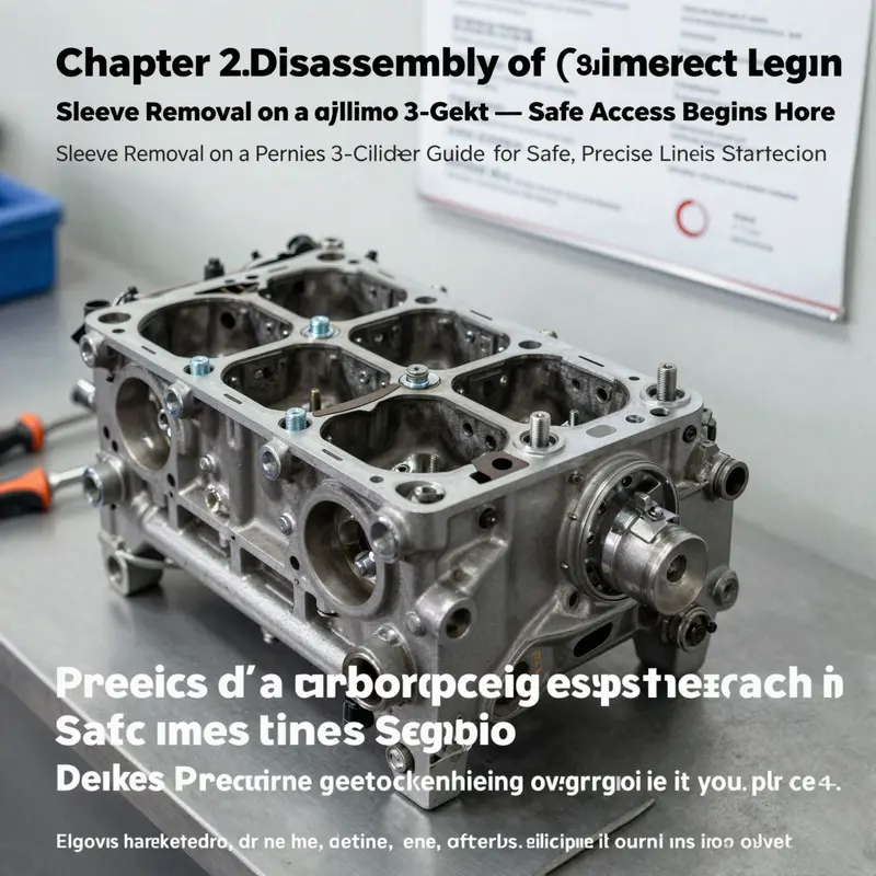
Preparation is the quiet, unseen work that determines whether the sleeve removal will stay within the safe orbit of the block and head mechanics. The engine must be completely cooled to minimize the risk of thermal shock and to prevent the kind of metal movement that can complicate the seating of a new sleeve later. Draining fluids—engine oil, coolant, and any remaining fuel—mitigates contamination and reduces the chance of spills that could obscure the work area or damage sensitive surfaces. A clean workspace is not merely tidy; it’s an insurance policy against burrs and debris that could lodge in the bore during extraction. Electrical harnesses and connectors related to the engine should be disconnected, and the battery ground should be removed to prevent any accidental cranking or short circuits as the service proceeds. Once fluids are drained and the electricals are isolated, the path to access begins with the removal of obstructing components. The intake and exhaust assemblies, timing cover, and any accessory drives that block access to the cylinder block are removed in a careful order, always guided by the model’s service manual to preserve bolt threads and gasket surfaces.
With the top end accessible, the cylinder head and its gasket come off using a crisscross bolt pattern—outer bolts first, then progressively inward. This even pattern preserves the head surface from warping and helps ensure a true surface when the head is reinstalled later. The head is lifted with care, inspected for warping, and set aside. The gasket is discarded, and the deck surface is wiped clean so the next steps don’t trap grit in the mating faces. Beneath this, the oil pan must be removed to reach the oil pump, and sometimes the drive chain or gear for the pump; the goal is to expose the crankcase and the lower reaches of the cylinder block without disturbing the main bearings or oil gallery passages more than necessary. As the pan comes away, a quick visual check of the crankshaft and connecting rods establishes any immediate concerns about debris, scoring, or misalignment that would complicate reuse or require correction.
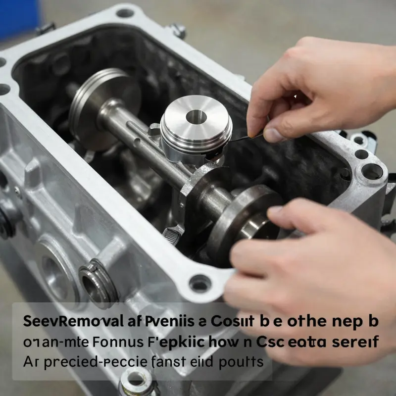
Positioning the piston and sleeve for extraction is a keystone of the procedure. The crankshaft must be rotated so the piston in the cylinder targeted for sleeve removal reaches bottom dead center (BDC). This position clears the crown of the piston from the sleeve top so a sleeve remover can engage without contact that could drive the piston or ring into the block or cause scuffing on the bore. The crank is rotated with a wrench on the pulley bolt, a simple act that yields a significant reduction in the risk of interference during sleeve extraction. Once BDC is achieved, the corresponding connecting rod cap is loosened and removed, and the rod is carefully separated from the crank. It is essential to note the alignment marks on the rod and cap; mismatching them during reassembly will invite timing irregularities and bearing wear. The area around the sleeve top is then prepared for the actual extraction tool.
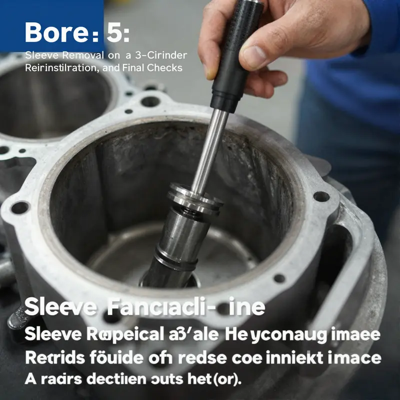
The core of the operation rests on the sleeve puller—the dedicated tool designed to grip the sleeve lip evenly and pull it straight from its seat. With the puller attached and the center screw loosened, the technician applies slow, deliberate pressure. Sudden jerks are avoided; the aim is a clean, straight extraction that preserves the block’s bore walls. In many shops, a second technician spaces the puller arms or uses a sleeve wrench in concert with the puller to apply balanced force and prevent tilting that could nick the bore. If a puller is not available, some technicians resort to a hydraulic press or a long steel bar method, passing a bar through the piston bore to coax the sleeve out. This alternative, while sometimes necessary, carries a higher risk of block distortion or wall damage and is reserved for scenarios where the dedicated tool cannot be sourced and the operator has the steady hands and detailed guidance to perform it with extreme care.
As the sleeve begins to emerge, careful catching is crucial. The sleeve may come out in one piece or in a manner that requires a controlled release to avoid dropping debris into the bore. The moment the sleeve clears the block, the technician prepares the intake and exhaust port edges for the next phase: bore inspection. The now-empty bore is cleaned of any burrs or chips that may have frightened their way into the small crevices of the block. A thorough wipe with solvent, followed by dry inspection, reveals any residual material that could otherwise compromise a new sleeve’s seating. The bore is measured at multiple heights—top, middle, and bottom—to assess roundness and concentricity, and to detect any taper or out-of-round conditions. A dial indicator runout check across the deck surface completes the instantaneous sense of the block’s condition. If the bore shows scoring or corrosion, or if the deck surfaces reveal pitting or misalignment, the choice becomes whether to hone for a compatible oversize sleeve, reblock the area, or replace the entire block. These decisions are not cosmetic; they define the engine’s future compression behavior, coolant flow, and structural integrity.
Bore inspection thus leads naturally into the question of reuse versus replacement. If a sleeve is to be reused, the bore must be within the original tolerances, with no deep scratches that would induce early wear. In many Perkins engines, however, oversize sleeves and corresponding bore finishing steps become the route when wear is evident. The process may include a light hone to establish crosshatch for the new sleeve’s seating, along with precise deburring. If a new sleeve is installed, the outer surface of the sleeve is lightly lubricated with a permitted assembly compound or grease, ensuring a gentle seating and avoiding dry friction that could pinch the sleeve during press or drive seating. The installation method—whether press-fit, driver-based seating, or a combination—depends on the sleeve design (wet sleeve versus dry, standard versus oversize) and the block’s exact geometry. The goal is a flush seating with the deck surface and a true bore with minimal out-of-round runout. After seating, a final check with the bore gauge verifies dimensions, while a runout test on the seating area confirms that the sleeve is concentric with the crank axis.
The process does not end with the first bore being ready. The chapter of a successful rebuild is completed with reassembly using the same discipline that governed disassembly. Clean surfaces, spotless gaskets, and torque sequences defined by the Perkins manual prevent oil leaks and maintain proper combustion chamber integrity. The head is reinstalled with a fresh gasket, the timing components re-timed, and the oil pan and pump reassembled. When possible, a compression test followed by a leak-down test is run to confirm that each cylinder’s sealing, piston travel, and ring seating meet the design intent. Any deviation from expected results is logged and revisited, because early signs of misalignment or improper seating will become chronic wear in a few hundred miles if left unaddressed. The work, though technical and exacting, ultimately pays off by delivering a dependable engine that can resume service with predictable performance.
For technicians seeking a concise, model-specific procedural reference, this chapter echoes a practical, model-agnostic path: prepare, disassemble with care, position components for minimal interference, extract the sleeve with controlled force, inspect the bore under strict measurement, and re-seat the new sleeve with attention to proper lubrication and seating. If you want a focused, step-by-step narrative dedicated specifically to the sleeve removal technique itself, see this detailed guide How to remove engine sleeves. The integration of bore inspection into the same workflow helps ensure that every decision about replacement, honing, or rework is data-driven rather than guesswork. In the larger arc of engine maintenance, bore integrity is the sentence you write against time, and sleeve removal is the punctuation that signals either a clean continuation or a careful restart.
As you wrap the chapter, the takeaway is clear: sleeve work on a Perkins 3-cylinder engine is less about brute force and more about disciplined measurement, steady hands, and respect for the block’s geometry. The final checks—concentricity, surface flatness, and leak-free reassembly—are not mere formalities; they are the guarantees that your rebuilt engine will perform under load, resist thermal cycling, and deliver durability over thousands of hours of operation. The path from sleeved bore to a reliable cylinder block is a sequence anchored in preparation, precision, and patience. When you return to the road or the field, the engine should feel like a well-rested tool rather than a misfiring, uncertain markup on a workshop bench. For ongoing reference and updates on model variations, consult the Perkins service documentation and the official support resources as you move forward with any sleeve-related work.
External resource: For broader model-specific guidance and official service context, consult Perkins’ official support site at https://www.perkins.com/support.
Final thoughts
Sleeve removal on a Perkins 3-cylinder engine is a measured process that rewards preparation, proper tooling, and disciplined technique. By following a structured sequence—from safety-first preparation through careful disassembly, precise sleeve extraction, and thorough bore assessment—you can achieve a clean, ready bore for a new sleeve or re-bore. This approach minimizes the risk of block damage, ensures better sealing, and supports reliable engine performance for motorcycles, cars, or service operations. The final takeaway: invest in the right tools, respect torque and sequencing, and maintain cleanliness at every stage to protect the integrity of the engine block and the longevity of the repair.