Removing a sleeve from an LS engine is a precision mechanical procedure that belongs in major rebuilds and high-performance builds. Whether you’re a motorcycle owner branching into V‑8 swaps, an auto owner maintaining a Camaro or Silverado, or a parts distributor or repair shop preparing for service work, understanding the full workflow prevents costly mistakes. This guide walks through five linked stages: preparing the engine and initial disassembly, accessing the cylinder block, choosing and applying the correct tools and extraction techniques, performing post‑removal inspection and cleaning, and knowing when to seek professional help and follow strict safety practices. Each chapter builds on the previous one so you can plan teardown, protect the block, extract sleeves cleanly, and verify the block is ready for re‑sleeving or machining.
Setting the Stage: Preparation and Initial Disassembly for Sleeve Removal in an LS Engine
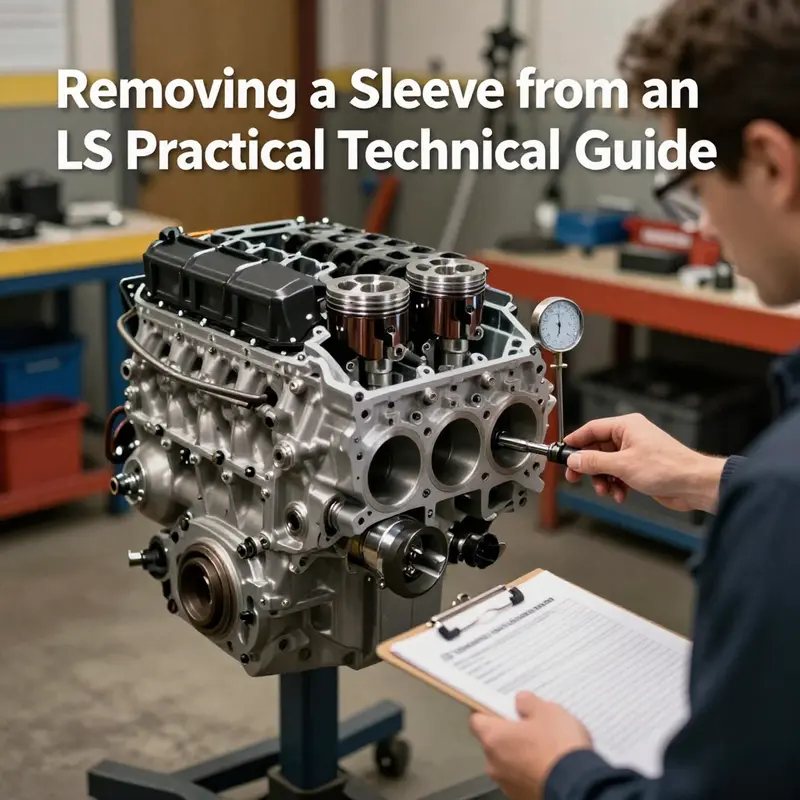
Removing a sleeve from an LS engine is as much about meticulous preparation as it is about the pulling process. The sleeve is a critical part of the cylinder block, and any misstep during prep or the early disassembly can translate into a warped bore, a damaged sleeve, or a compromised block. The goal of this chapter is to establish a careful, repeatable flow that preserves the integrity of the block while giving you reliable access to the sleeves for removal and eventual re-sleeving or refurbishment. What follows is a narrative of preparation that treats the engine as a precision machine, not a pile of parts to be shuffled aside at will.
First comes safety, environment, and stability. The engine should be on a solid stand or a well-anchored workbench, not dangling from a hoist or resting on an improvised cradle. The work area must be clean, well lit, and free from clutter that could shed debris into the open cavities. PPE is non-negotiable: safety glasses, gloves with good grip, and sturdy footwear are essential. The engine must be completely cooled before any disassembly begins because the sleeves extend into aluminum or composite block walls, and thermal shock or heat-induced distortion can compromise the bore. Once the engine is stable, the next steps focus on removing life-support systems and preparing the workspace for fluids. Draining all fluids—engine oil and coolant—helps prevent spills, reduces the risk of cross-contamination, and makes the area safer when components are moved and laid aside. Disconnecting the negative battery lead is a prudent precaution, eliminating the possibility of accidental ignition or short circuits while you work among exposed metal surfaces and unplugged harnesses.
With power safely isolated and fluids drained, the path to the sleeves becomes a corridor of access that requires some external components to come off. The LS engine family is designed with serviceability in mind, but the access path is not a walk in the park. The intake manifold, exhaust headers or manifolds, valve covers, the timing cover, water pump, and, in many designs, the oil pan must be removed or loosened to create room to reach the cylinder block. The goal is not to rush but to create space without bending fragile components or misaligning gasket surfaces on reinstallation. During this phase, label every part and every fastener, and document the orientation of items that might not be identical from one bank to the other. A simple marking strategy—numbers on each bolt or a color-coded tag system—helps when reassembly time comes and reduces the risk of misplacing a part or reassembling in the wrong sequence.
Accessing the cylinder heads is usually the next major hurdle in preparation. The heads sit atop the block with a complex web of gaskets, shims, and bolt patterns. A careful bolt-removal sequence is essential to avoid warping the head or the deck surface. When the heads are removed, the pistons and connecting rods are partially exposed, and the top end becomes more accessible for the subsequent steps. Depending on the engine’s design and your intended approach to sleeve removal, it may be necessary to remove main bearing caps, rod caps, and even the crankshaft to expose the lower portions of the cylinder bores. This step must be approached with respect for the tolerances involved in the crank and bearing surfaces and with an eye toward preserving crankshaft alignment and the positional integrity of each cap. Each bearing shell and cap is unique to its location; misplacing them can lead to a headache during reassembly.
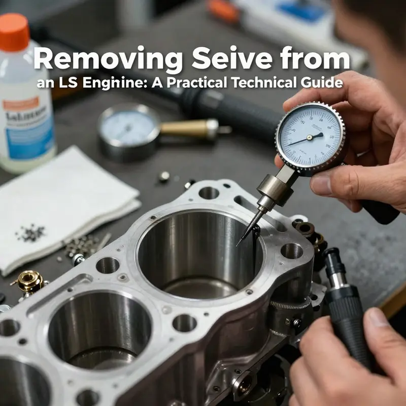
Throughout this phase, a meticulous approach to inspection becomes a companion to the mechanical work. Before any hardware is disturbed, visually inspect the cylinder bores for heat-check cracks, corrosion, scoring, or unusual wear that would imply prior overheating or machining that has altered bore geometry. Any anomalies should prompt a pause to reassess the plan for the sleeve removal. If the bore shows damage that might compromise the sleeve’s seating or the block’s structural integrity, the operation should be paused and evaluated by a machine shop with experience in block work. Marking the bores with a light indelible marker, and noting the bore number, thickness, and any observed flaws, helps to ensure a consistent reference during later steps and reassembly. The act of marking is not merely for memory; it is a safeguard against bores being mixed up or miscounted, which can lead to improper sleeve sizing or misalignment.
The transition from bore inspection to sleeve removal is where the process turns from a general disassembly into a precision operation. The LS sleeves are pressed into the cylinder walls and can be either dry sleeves or wet sleeves depending on the model and application. The distinction matters because it informs how coolant passages are routed around the sleeve and how aggressively you must treat the bore when extracting the sleeve. Dry sleeves, being surrounded by dry block material, require careful handling to avoid scuffing or marginal damage to the bore, while wet sleeves introduce coolant channels that demand even more care to prevent contamination or inadvertent coolant flow into the opposite bore. As you prepare to remove the sleeve, you must also prepare the workspace for the potential of residual pressure or slight movement in the sleeve interface. This is not a moment to improvise; it is a moment to rely on the correct tool geometry and a controlled application of force.
A genuine sleeve-removal operation rests on the right tool geometry and a patient, even application of force. A dedicated sleeve-puller or extractor tool is designed to grip the outer edge of the sleeve and apply pressure with a threaded mechanism that translates small, controlled increments into the movement required to release the sleeve from its press-fit. The technique is intentionally slow and even. If the sleeve is stubborn, a small amount of penetrating oil in the interface is sometimes used to ease the initial break of the press fit, but this must be done with caution to prevent oil from migrating into the bore where debris could compromise the next machining steps. Most importantly, the block surrounding the sleeve must remain free of nicks and gouges as the tool withdraws the sleeve. Any damage to the block wall can alter the bore geometry or compromise the sleeve-replacement process, leading to costly repairs.
As the sleeve begins to move, the operator must monitor for signs of misalignment or binding that could indicate a burr, a misdrilled port, or an imperfect bore edge. The removal sequence should be uniform across the bore banks to minimize any uneven load on the deck surface. Once the sleeve is out, the bore must be inspected again with the same eye for micro-cracks, chatter marks, or residue from the sleeve’s press-fit. Debris in the bore is a common enemy; even tiny metallic shavings can become abrasive particles during subsequent machining steps or when the new sleeve is pressed in. Cleaning must be meticulous: use lint-free wipes, solvent compatible with aluminum and iron alloys, and a bright light to catch any overlooked flecks. The cleaner the bore, the greater the chance of achieving a true, even press-fit for the new sleeve and the integrity of the deck sealing surface.
The discussion above naturally leads to the next practical step: confirming sleeve sizing and the proper seating method. The manufacturer’s specifications dictate the sleeve diameter, the wall thickness, and the interference fit required for a reliable seal and long-term durability. Without precise sizing and a clean, burr-free bore, the sleeve will not seat correctly, and the risk of oil leaks or coolant intrusion will rise. If you are not equipped with a reliable micrometer, bore gauge, and a controlled press tool, seek professional help from a machine shop that regularly handles LS-block work. This is not a place to experiment with improvised devices or “close enough” measurements. A proper re-sleeving, when indicated, includes verifying bore roundness, checking for taper, and confirming the parallelism across the cylinder walls.
The chapter you are reading is about preparation and initial disassembly, a foundation for the more exacting sleeve-removal procedure that follows. It emphasizes that success hinges on discipline: a clean workspace, careful labeling, thorough bore inspection, and an understanding of the sleeve’s engagement with the block. It is tempting to rush, especially when the system seems straightforward, but the sleeves are engineered components whose seating and integrity depend on a measured approach. A good practice is to pause after each major milestone—after draining fluids, after removing the external components, after head removal, and after exposing the bores—and reassess your plan against the observed conditions. If anything deviates from expectation, take time to re-check torque patterns, gasket seating surfaces, and bore geometry before continuing.
For readers seeking a broader procedural reference that aligns with the principles described here, a focused how-to on engine-sleeve removal provides a step-by-step companion to this preparation phase. See the detailed guide How to remove engine sleeves for additional context on tool usage, bore cleaning, and the nuances of dry versus wet sleeves, while keeping all safety and cleaning practices in view. As you move toward the actual sleeve extraction, remember that every LS block is a complex, precision-built component whose longevity depends on methodical care at every turn.
In the next section, we will translate this groundwork into the actual sleeve-pulling sequence, highlighting how to apply even pressure, how to monitor the sleeve’s movement, and how to protect the surrounding block during withdrawal. The aim remains consistent: remove the sleeve cleanly, inspect the bore for any latent damage, and prepare the block for the re-sleeve or further machining with the same care that guided the prep stage. For those who want a broader technical framework beyond the step-by-step, the following external reference offers a deeper look at sleeved blocks and their long-term considerations: https://www.monsterengines.com/blog/ls-block-sleeving-guide.
Unlocking the Core: Comprehensive Access to LS Engine Cylinder Block Components for Sleeve Removal
Removing a sleeve from an LS engine is a precise and delicate procedure that hinges on gaining meticulous access to the core cylinder block components. This phase is fundamental since the sleeve itself resides deep within the engine block, surrounded by pistons, connecting rods, and sealed cylinder heads. The process demands careful disassembly, methodical inspections, and the use of specialized tools to avoid collateral damage that can compromise the engine’s integrity.
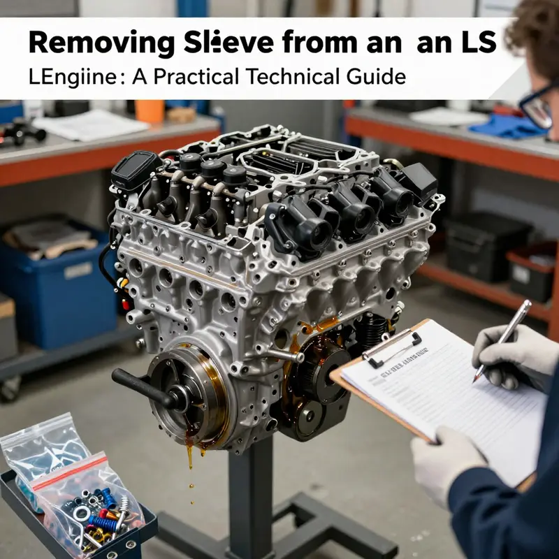
To begin, all peripheral components must be completely removed to expose the cylinder block. This typically includes the intake manifold, exhaust manifolds, valve covers, timing cover, and oil pan. Each of these parts plays a role in sealing or facilitating the engine’s operation but must be disconnected in a precise manner. Careful organization and labeling of every bolt, latch, and sensor disconnected during this phase are critical to ensure an efficient and mistake-free reassembly later.
Once external components are cleared, the cylinder heads—among the most critical engine parts—must be taken off. Removing the heads involves loosening head bolts following the manufacturer’s recommended bolt removal sequence. This step is essential to prevent warping or cracking, which can result from uneven stress distribution if bolts are loosened haphazardly. Given the LS engine’s aluminum block and often aluminum heads, protection against warpage is particularly important since aluminum expands and contracts more significantly with heat variations.
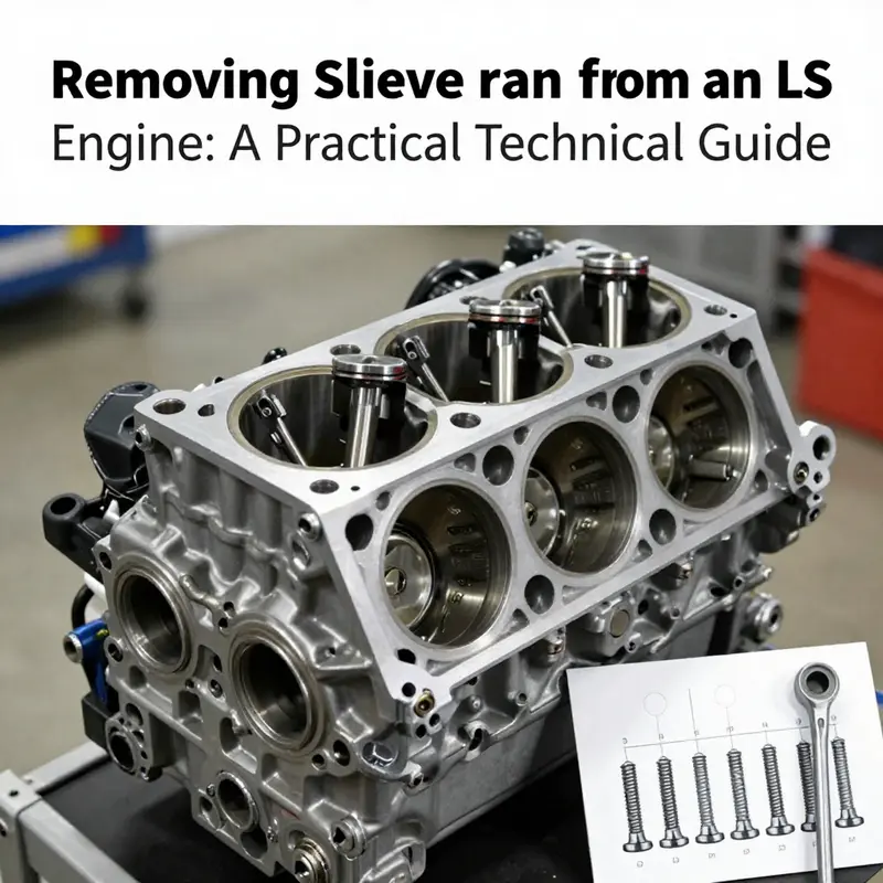
With the cylinder heads removed, the next components to address are the pistons and connecting rods housed within the cylinder bores. Accessing these involves rotating the crankshaft to position pistons at their lowest point, allowing room to safely extract them from the block. Special tools such as piston ring compressors must be employed when reassembling, but during removal, devices like piston pullers or carefully applied hand pressure will facilitate safe extraction. It is vital to proceed gently, avoiding any contact that could score or otherwise damage the cylinder walls, as even slight abrasions can negatively influence engine performance post-repair.
Extracting pistons leaves the cylinder sleeves—the metal liners which rest within the block bores—fully exposed. LS engines typically use sleeves pressed tightly into the aluminum block, often constructed from cast iron or steel alloys. This press fit requires precision to both install and remove, as the sleeve’s tight fit ensures durability but also poses risks of damaging the aluminum block if improper force is applied.
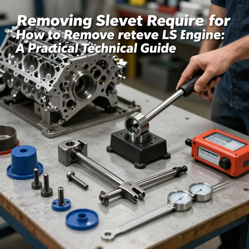
At this juncture, a dedicated sleeve puller tool is indispensable. This tool has specially designed gripping claws that attach firmly to the sleeve’s outer edge. When activated, usually through a threaded bolt mechanism, the tool applies steady, controlled force to extract the sleeve uniformly. Rushing this step or using uneven force risks cracking or deforming the surrounding block material, which would severely undermine the engine’s usability.
Maintaining cleanliness during this phase cannot be overstated. The working environment and all tools must be meticulously clean to prevent any dirt or debris from entering the cylinder bores. Contaminants inside the block can cause significant damage once the engine is reassembled and running, leading to premature wear or catastrophic failure. The block itself should receive a thorough cleaning and a detailed inspection at this stage, including checking for cracks, gouges, or uneven wear that might have developed over time or during the sleeve removal process.
Inspection may also reveal whether machining or honing of the block cylinder walls is necessary to achieve a flat, smooth surface before installing new sleeves. Following the engine manufacturer’s guidelines and work tolerances at this point ensures the engine’s longevity and optimal performance after rebuilding. In cases where damage is detected beyond routine wear, consulting a professional machine shop is advisable for precision repairs or modifications.
Another vital aspect when working on LS engines is recognizing the differences between dry and wet sleeves. Some LS variants incorporate wet sleeves, which allow coolant to circulate around the sleeve, aiding in thermal management. These sleeves require even more careful handling since coolant passages can be damaged or obstructed if the sleeve is extracted improperly. Dry sleeves do not have these passages but still require delicate attention due to their press-fit nature.
To achieve the highest quality results, users should always reference the official GM Service Manual for their specific LS engine model, such as the LS1, LS3, or L92. These manuals provide precise torque specs, step-by-step guidance, and safety precautions tailored to the engine’s design nuances. For those seeking additional detailed support, professional automotive platforms offer comprehensive repair manuals and diagnostic information critical for a successful sleeve removal and replacement.
During reassembly, reverse procedures are followed with heightened awareness of cleanliness, torque precision, and component alignment. Pistons must be reinserted with ring compressors, connecting rods reattached with proper bearing clearances, and cylinder heads reinstalled following torque sequences. The use of precision tools at each step minimizes the risk of engine failure and optimizes performance.
Understanding and mastering the critical step of accessing and preparing the cylinder block components forms the backbone of removing a sleeve from an LS engine. The complexity of the process goes far beyond simple removal, demanding respect for the engine’s engineering, stringent cleanliness standards, and exacting mechanical discipline. This foundational work sets the stage for all subsequent operations to rebuild or upgrade these powerful and popular engines effectively.
For those interested in a visual demonstration of the specialized tools and precise techniques required during this access and removal phase, the How to Remove a Cylinder Sleeve from an LS Engine – YouTube (2023) video offers a valuable step-by-step guide.
Furthermore, for enthusiasts or professionals looking to deepen their mechanical skills, exploring additional resources on essential engine upgrades for performance can complement the understanding gained from sleeve removal and cylinder block preparation.
The Gentle Art of Sleeve Extraction: Mastering LS Engine Cylinder Sleeve Removal
Removing a cylinder sleeve from an LS engine is a precision-driven task that sits at the intersection of careful disassembly, clean machining, and disciplined reassembly. It isn’t a routine maintenance job; it’s a rebuild-level operation that can determine the durability and performance of a rebuilt engine. The LS family, with its aluminum block configurations and the varied sleeve implementations across generations, requires respect for what the sleeves do and how they interact with the bore, the block, and the cooling system. The goal is not merely to yank a sleeve out but to extract it in a controlled, repeatable manner so that the bore remains true, the block stays intact, and the path remains open for either a fresh sleeve or a nearby bore modification. In practice, this means starting with a clean slate and proceeding with a plan that honors the material properties of the block, the sleeve, and the surrounding journals.
Preparation is the foundation. The engine should be cooled completely before any work begins. Thermal contraction can influence how stubborn a sleeve might be and can also affect the integrity of nearby components if heat is introduced too aggressively. Drain all fluids—engine oil, coolant, and any lingering fluids in the crankcase or cooling passages—to minimize the risk of spills and to prevent any contaminants from migrating into the bore once the sleeve release begins. External components that obscure the sleeve—intake and exhaust manifolds, valve covers, timing cover, and the oil pan—must come off so the cylinder block is accessible. In these moments, a careful map of components is invaluable. Marking the pistons’ positions, the connecting rods, and the bore orientation helps avoid reassembly guesswork, and it provides a blueprint for the teardown that follows.
Access to the cylinder block demands disciplined steps. Most LS engines feature an aluminum block with cylinder sleeves pressed into the bores. Sleeves may be cast iron or steel, dependent on the model year and the intended performance application. It is here that the sleeves’ interface with the bore becomes critical: any misalignment or uneven force during removal risks wall scoring, tapering, or even a hairline crack in the block wall. The sleeve itself is the target of the extraction, but the surrounding material must be treated with equal care. Before the actual removal, the cylinder heads are removed in a sequence that minimizes warping risk on the block and ensures that the block is in a stable, uniform state for the sleeve work. The main bearings, rod caps, and possibly the crankshaft might be removed if they impede access to the bore perimeter or if the sleeve edge is flush with, or slightly protruding from, the bore line. In many rebuild scenarios, the bore’s concentricity and the smoothness of the bore surface after sleeve withdrawal are as important as the sleeve’s own integrity. The goal is a bore that is free of deep scratches or distortion, ready for inspection or re-sleeving, depending on the plan for the engine build.
The actual extraction hinges on a specialized tool and a patient approach. A sleeve puller is the centerpiece of this operation. It grips the outer edge of the sleeve and uses a threaded center bolt to apply controlled, even pressure. The puller’s jaws must seat squarely on the sleeve’s perimeter, with alignment checked to ensure no tilt that could score the bore or mushroom the sleeve edge during removal. If the sleeve is initially bound by rust, corrosion, or heat-related adhesion, a light tap with a hammer on the puller’s center bolt can help to break the bond. The key is to apply force gradually and evenly, not with a single abrupt push that can distort the bore or pull in misalignment. As pressure is applied, the sleeve begins to slide from the block. Patience is essential because aggressive force can quickly translate into expensive block damage. In addition to the puller, a few ancillary tools aid the process: a clean selection of sockets for fastener removal, a pry bar to nudge the sleeve’s edge where necessary, and a crescent wrench for incidental adjustments around the periphery. Throughout, a clean environment matters. Debris in the bore can scratch the wall, and loose grit can contaminate new sleeves or the next stage of machining.
The removal sequence should be slow, deliberate, and well-documented. Begin by verifying the puller’s alignment over the sleeve. Any misalignment means the sleeve will bind or the block wall will take the brunt of the load. With the center bolt engaged, advance slowly. A minute amount of torque, repeated over many seconds, prevents jerky movements that could crack or chip the bore edge. If resistance persists after several careful revolutions, stop and reassess. It may be necessary to double-check the bore for any surface obstruction, to re-clean the area, or to re-seat the puller to regain a symmetrical grip. In some cases, gentle tapping on the very top of the sleeve with a soft hammer or non-marring mallet can help to release surface corrosion that has created a stubborn seal. This is not a shortcut; it is a controlled, initial intervention that should be followed by continued steady pulling. Once the sleeve begins to move, it will usually travel with the same measured pace as the puller’s bolt turns, revealing the sleeve’s edge and, finally, liberating it from the block.
Post-removal inspection is the moment when the truth of the bore comes into sharp relief. The cylinder bore must be checked for cracks, chips, or scoring. Even minor damage can compromise ring seal and oil control in a rebuilt engine. The bore should be cleaned to remove any residual sleeve material or debris and then measured for roundness and taper. Any signs of damage typically signal the need for machine work—either honing, boring, or even re-sleeving the block depending on the engine’s overall rebuild plan. If the bore is deemed still repairable, the next steps may involve preparing the surface for a new sleeve, which includes deburring the edge, removing sharp corners, and ensuring a uniform surface that a fresh sleeve will seat into. If the decision is to replace the sleeve, precise sizing is non-negotiable. The sleeve must be properly sized and pressed in to the manufacturer’s specified interference fit. The method chosen for pressing in a new sleeve depends on the sleeve material and bore condition, but in every case, cleanliness and alignment are again the watchwords. A dry assembly mindset requires careful alignment checks, and where coolant passages are involved (wet sleeves), the process must account for the cooling interface to avoid leakage paths or improper contact.
Among the practical cautions that recur in sleeve work are the risks of over-zealous attempts, misalignment during pull, and underestimating the importance of clean surroundings. A successful extraction rests on disciplined preparation, a properly matched puller, and a patient tempo. It is also wise to adopt reference materials and service manuals that reflect the exact LS variant you are dealing with—whether it is an LS1, LS3, or another member of the family. Those manuals provide the precise torque specs, bolt patterns, and procedural subtleties that keep the project on safe footing. While some guidance exists in broad terms, the details matter, especially when dealing with aluminum blocks and sleeves designed to handle high combustion pressures and heat. If you are not confident in reading bore geometry, in performing precise measurements, or in the use of a puller, seek the involvement of a professional machine shop. A shop equipped for engine block work can verify bore condition, perform the necessary machining, and confirm that the sleeve installation meets all tolerance requirements.
The inner philosophy of this process is that sleeve removal is a step in a broader objective: to restore or elevate engine reliability. It is not an isolated impulse to make a change. As you prepare to install a new sleeve or to modify the bore for a different sleeving configuration, the surrounding systems—cooling, oiling, and the block’s structural integrity—must be considered in tandem. That means keeping the work area clean, verifying the alignment of all references, and rechecking each component’s orientation during reassembly. The narrative you follow through the teardown should map to the planned rebuild path, not merely the misadventure of forcing pieces together in a hurry. The guidance from a formal service manual remains a reliable compass here, and supplementing that with careful, hands-on assessment in a well-equipped shop provides the most robust path to a durable result. If you want a concise, visual walk-through of the sleeve removal process, you can reference a detailed video guide that presents the technique in action and adds a layer of practical context to the steps described above: How to Remove Engine Sleeves.
In the broader arc of a rebuild project, sleeve removal is a pivot point that can determine the next phases—whether that means re-sleeving, boring, honing, or selecting a different sleeve material for enhanced thermal management. The careful decisions made here ripple through cooling efficiency, friction, and engine longevity. The discipline you bring to measuring bore geometry after removal, to cleaning every surface before further machining, and to documenting each step becomes the quiet backbone of a successful rebuild. It transforms a technically demanding job into a workflow that minimizes risk and aligns with the engine’s long-term performance goals. As you proceed, keep the narrative of precision alive in every action—from the initial teardown to the final reassembly—and let the sleeve’s departure be a measured act that signals the readiness of the block for the decisions that follow.
External resource for visual reference: https://www.youtube.com/watch?v=QfLX8a0wBbY
Thorough Post-Removal Inspection and Cleaning for LS Engine Sleeves
A rigorous inspection and cleaning routine after removing a sleeve from an LS engine is as important as the extraction itself. After the sleeve comes out, the block and related components are exposed and vulnerable. Dirt, metal fragments, residual sealant, and old gasket material left behind can compromise sealing surfaces, impede coolant and oil flow, and cause premature wear. Treat this phase as a precision step: your goal is to reveal the true condition of the cylinder bores, seal surfaces, bolt holes, and oil and coolant passages, then restore them to a state that allows safe, reliable reassembly or further machining.
Begin by establishing a clean workspace and maintaining a contamination‑controlled environment. Lay out clean, lint‑free covers to protect exposed cylinders and journals from airborne debris. Use magnetic trays for fasteners and components so nothing gets lost or mixed up. Grounding is important—disconnect the battery if not already done—then wear nitrile gloves to keep oils and skin oils off sealing surfaces. Wherever possible, keep a shop vacuum and clean compressed air handy to remove loose particles immediately rather than wiping them back into crevices.
Start your inspection with a visual sweep of the block deck and the exposed cylinder bores. Look for small, telltale signs first: hairline cracks radiating from the sleeve register, pitting near coolant passages, unusual scoring inside bores, or spots where the sleeve’s outer edge gouged the block during removal. Use good lighting and a loupe or inspection lamp to reveal finer defects. If you find any suspicious cracks around the sleeve seat or in the deck surface, stop; these can compromise the block’s structural integrity. At that point, a machine shop assessment is required because welding or sleeving repairs beyond simple honing may be needed.
Next, clean the sealing surfaces thoroughly but gently. Old gasket material, silicone, and residual gasket sealer can be stubborn; use a plastic or brass scraper to remove them. Avoid steel scrapers or sharp chisels that can mar the aluminum deck. After mechanical removal, apply a solvent appropriate for engine surfaces and wipe with lint‑free towels. A soft nylon brush helps dislodge trapped residue from bolt holes and oil passages. After solvent cleaning, blow out all cavities and passages with compressed air, holding a rag downstream to capture expelled debris. Make sure threads are free of debris; inspect for cross‑threading or stripped areas. Minor damaged threads can be chased with the correct thread chaser, but replace any severely compromised studs or bolts.
Cleaning the bores requires particular care. After sleeve extraction there will likely be burrs and raised edges on the sleeve seat. Use a deburring tool designed for cylinder bores to gently chamfer the exposed edge, but do this sparingly—over‑removing material can change the sleeve interference fit for a new sleeve. Remove all metallic chips with a vacuum first, then wipe with a solvent soaked rag. Use a bore brush sized to the cylinder to scrub away build‑up. Follow with compressed air to clear fines. If you have a parts washer, a cycle in the washer will remove oil and particulate without aggressive rubbing. Finally, wipe the bore with a clean, oil‑free cloth to confirm it is spotless.
Inspect coolant and oil galleries next. Channels that route coolant around the sleeve or through the deck can collect scale, residual sealant, and metal fines. Use appropriately sized bottle brushes and solvent to clean these galleries. Flush them with clean water if your situation allows, but ensure the block is completely dry before proceeding—compressed air and a heat lamp help. For oil galleries, use solvent and compressed air only; water in oil passages leads to long drying times and corrosion risks. Check the passages visually with a bore light or inspection camera if available. Blocked or partially restricted passages can cause cooling or lubrication failures after reassembly.
Examine the sleeve seating surface for flatness and concentricity. While the block deck should be sent to a machine shop for machining if you suspect warpage, you can perform a basic flatness check at the bench using a precision straightedge and feeler gauges. Lay the straightedge across the deck at multiple orientations and check for gaps with feeler gauges. Tiny deviations under a few thousandths may be acceptable depending on specifications, but wider gaps or a rocking straightedge indicate the need for professional milling. Similarly, check bore concentricity with a dial bore gauge if you have access; this reveals whether the sleeve sat true or if the block has distortion that needs correction.
The condition of bolt holes and sleeve locating features is critical. Clean each bolt hole using a thread chaser; do not use a tap that removes material. If the sleeve locating ledge looks damaged, photograph and measure it carefully. The locating ledge must be restored to spec or the new sleeve may not seat correctly, resulting in coolant leaks or misalignment. If the sleeve was a wet sleeve—one exposed to coolant—inspect the contact area for pitting or erosion from electrochemical corrosion. Wet sleeve regions need extra attention because damage there often requires machining or replacement sleeves.
After cleaning and initial inspection, decide which items must be replaced. Seals, O‑rings, and gaskets removed during sleeve extraction should be replaced as a rule. Bolts that were stretched or showed signs of corrosion should be discarded and replaced with specified torque‑to‑yield or OEM grade fasteners. Any sleeve that shows signs of damage, cracking, or scoring should not be reinstalled. When in doubt, plan for new sleeves and new fasteners—reliability depends on these small parts.
Before installing new sleeves or sending the block for machining, protect the finished surfaces. Plug oil galleries and coolant passages with clean, lint‑free plugs, and cap the bores with cardboard or plastic covers to prevent dust ingress. Place a layer of light oil on machined surfaces to prevent oxidation if reassembly is delayed. Document everything with photos and notes: torque specs previously recorded, orientation of components, and any measurements taken during inspection. This documentation will be invaluable during reassembly or when communicating with a machine shop.
If the inspection reveals damage beyond routine cleaning—cracked deck, warped surface, damaged sleeve register—consult a professional machine shop immediately. Repair options include deck milling, reboring and aligning sleeves, or installing different style sleeves designed by professionals. A machine shop can perform pressure testing, magnetic particle inspection, or dye penetrant inspection to reveal hidden cracks. They also provide precise machining tolerances necessary for proper sleeve fit and seal integrity.
Maintain records of all inspection findings, parts replaced, and measurements. These records are part of the engine’s history and help track performance after reassembly. If you plan performance upgrades, consider this inspection report when choosing sleeve materials and finish specifications. Proper installation of new sleeves depends on accurate measurements taken now: sleeve interference, deck flatness, bore diameter, and runout will determine whether press‑fit or different installation methods are required.
Finally, if you want a concise primer on sleeve removal and what follows it, consult a focused resource on engine sleeving principles like this guide on how to remove engine sleeves. For official torque specs, disassembly sequences, and variant‑specific procedures, refer to the manufacturer’s service documentation or an authoritative repair manual such as those recommended in professional service databases.
By treating the post‑removal phase as a precision step, you preserve the block’s integrity and set the stage for a successful sleeve installation or full rebuild. Clean, document, and measure meticulously; when in doubt, stop and seek machine shop input rather than proceeding with uncertain repairs.
External reference: https://www.haynes.com/
Ensuring Safety and Precision: Expert Practices for Removing Sleeves from LS Engines
Removing a cylinder sleeve from an LS engine is a task demanding expert precision, thorough preparation, and strict adherence to safety protocols. This process is not merely mechanical extraction but a critical intervention within an engine rebuild or performance upgrade. Any misstep can irreversibly damage the engine block or compromise its long-term reliability. Due to the aluminum construction of LS engine blocks—characteristic of Chevy models such as the Camaro, Corvette, and Silverado—the margin for error is minimal. The aluminum alloy, while lightweight and strong, is softer than cast iron and more susceptible to deformation or cracking if sleeves are removed improperly. Therefore, meticulous planning coupled with specialized tooling is essential to conduct sleeve removal with the highest level of professionalism and safety.
The process begins with comprehensive engine preparation. The first priority is confirming the engine is completely cooled. Working on a warm or hot engine introduces risks of burns and complex thermal expansion effects, which can change the dimensions of engine components. It’s critical to drain every fluid from the engine — including oil and coolant — to avoid spills that could cause workplace hazards or damage sensitive parts during disassembly. Once fluids are evacuated, the engine must be disassembled down to the bare block, removing the intake manifold, cylinder heads, valve covers, oil pan, timing cover, pistons, connecting rods, and crankshaft if necessary. This teardown exposes every component needed for safe, unrestricted access to the sleeves.
Marking and documenting every component during disassembly is an expert practice that ensures smooth reassembly. Each sleeve should be clearly labeled with its corresponding cylinder number. Cylinder sleeves, often called liners, are rarely interchangeable because they are precisely machined and press-fit to accommodate minute variations in the block. If sleeves are mixed, it can lead to poor sealing surfaces, uneven heat dissipation, and ultimately engine failure. Careful documentation avoids such risks, giving the technician certainty that each sleeve returns to its original position.
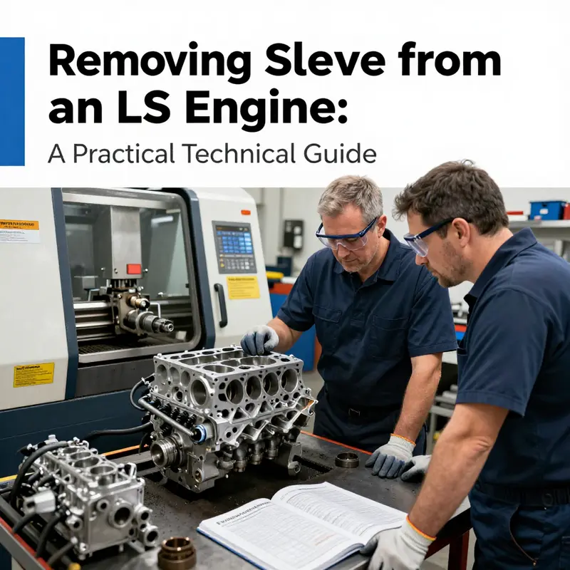
The next major consideration involves the choice and use of tools. Removing sleeves without the correct specialized equipment is one of the most frequent causes of damage in LS engine rebuilds. Conventional hand tools like hammers or chisels are strictly prohibited. These implement sharp impacts or uncontrolled forces which easily mar or crack the aluminum block surface, requiring costly repairs or scrap. Instead, operators rely on precision hydraulic presses equipped with tailored fixtures designed specifically for LS sleeves. These fixtures align the sleeve concentrically, allowing forces to be applied evenly and gradually along the longitudinal axis of the sleeve.
During hydraulic press operation, alignment is paramount. Even slight off-center pressures cause uneven stress patterns, increasing the risk of sleeve fractures or warped bores. Expert machinists validate fixture positioning before applying force, verifying that all components are perfectly parallel. This attention to detail extends beyond positioning—for example, to the speed and steadiness of pressure application. Taking time to apply gradual force reduces shock loads inside the block, preventing microfractures that could later evolve into catastrophic damage. Operators wear comprehensive personal protective equipment (PPE), including eye protection and gloves, since sudden sleeve release can propel parts forcefully.
Once the sleeve is pressed out, professional practice dictates a rigorous inspection phase. The cylinder bore is scrutinized for any signs of cracking, warping, or abnormal wear. This step is non-negotiable, because even minor defects in the bore can jeopardize the entire rebuild. The inspection encompasses visual checking aided by magnification and measuring instruments such as bore gauges, dial indicators, and micrometers. These tools verify that the bore’s geometry falls within manufacturer specifications.
If inspection confirms the bore is free from damage, cleaning follows. Removing residual debris and contaminants preserves the integrity of any subsequent installation, whether that involves new sleeves or direct machining. If damage is identified, the block may require corrective machining such as line boring, honing, or in extreme cases, replacement. These decisions hinge on the severity of the defect and operational goals.
Throughout this entire procedure, referencing the official service documentation from General Motors is crucial. The LS Engine Service Manual (2023 Edition) comprehensively details torque specifications, disassembly sequences, torque values, and tool recommendations. It presents authoritative information essential for both novice and veteran engine builders to meet manufacturer standards and maintain engine warranty compliance.
Attempting this operation without sufficient knowledge or professional tools can cause permanent damage to the engine block, leading to costly failures and lost labor. Therefore, it is strongly advised to either receive formal training or perform sleeve removal under experienced supervision. If in doubt, entrusting the procedure to a professional machine shop ensures adherence to best practices and utilizes specialized equipment not readily available in typical home garages.
This chapter underscores the gravity of removing sleeves from an LS engine, reinforcing the value of caution, precision, and professional guidance. The combination of thorough preparation, accurate documentation, proper tool use, deliberate press operations, and detailed post-removal inspection defines the standard of excellence for sleeve removal. Adhering to this framework helps preserve the integrity and performance of the engine block, ultimately safeguarding the investment in any LS engine rebuild or upgrade.
For those interested in expanding their knowledge on engine component care and upgrades, exploring essential engine upgrade strategies can provide meaningful insights on related maintenance and enhancement techniques.
For detailed, step-by-step procedures, torque specs, and technical diagrams, consulting the official General Motors LS Engine Service Manual (2023 Edition) is highly recommended. This resource offers the comprehensive guidance necessary to ensure that cylinder sleeve removal is performed safely, professionally, and effectively.
Final thoughts
Removing a sleeve from an LS engine is a methodical operation that rewards planning and discipline. Correct preparation and disassembly protect the block and make sleeve extraction accessible; careful access to cylinder components preserves orientation and bearing surfaces; the right tools and controlled extraction techniques prevent damage and ensure even sleeve withdrawal; thorough post‑removal inspection and cleaning confirm whether the block can accept new sleeves or needs machining; and professional guidance plus strict safety practices bridge the gap for shops and owners who lack specialized equipment. For motorcycle owners and auto enthusiasts taking on an LS rebuild, for parts distributors advising customers, and for repair shops committed to quality, the consistent theme is the same: take time, use the correct tools, document every step, and consult a machine shop when in doubt to protect the investment in the engine block.