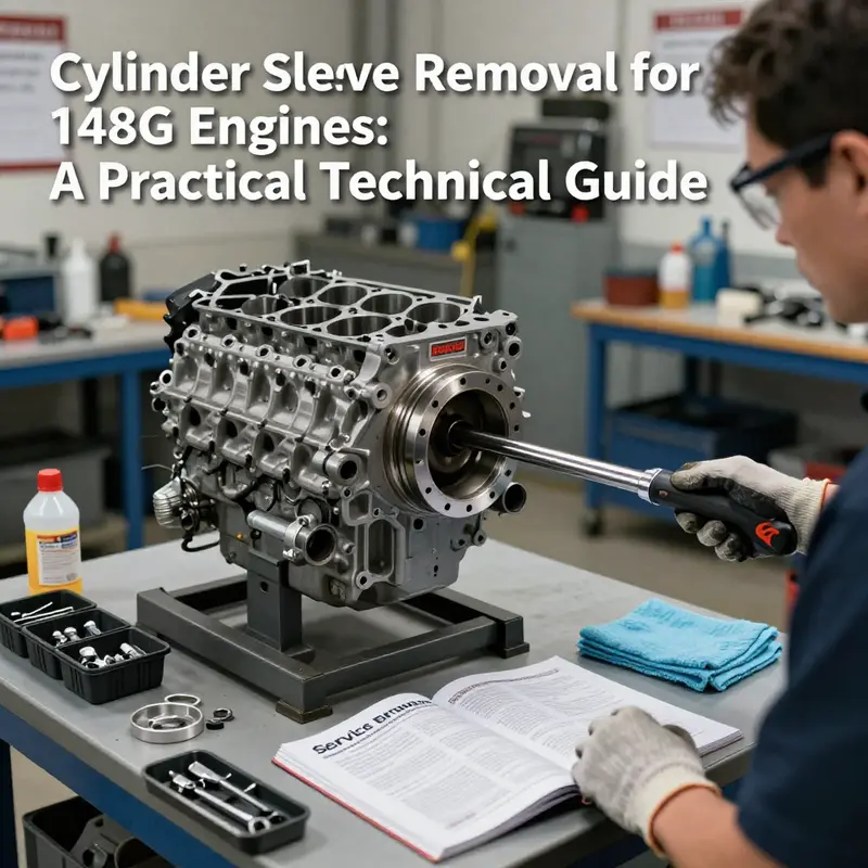
Removing cylinder sleeves from a 148G engine is a service-level job that intersects careful safety practice, correct tooling, and precise inspection. For motorcycle and auto owners, parts distributors, and repair shops, understanding the workflow reduces risk, protects the block, and speeds turnaround. This guide breaks the task into three focused chapters: Preparation and Safety to secure the engine and work area; Using Tools and Extraction Techniques to show how to use a sleeve puller and extraction sequence; and Inspection, Cleaning, and Model-Specific Guidance to evaluate the bore and prepare for replacement. Each chapter links directly to the central task of sleeve removal and builds the practical knowledge needed to complete the job reliably.
null
null
Sleeve Extraction Mastery: Precision Tools and Techniques for the 148G Engine
In the world of heavy‑duty engines, the cylinder sleeve sits as a quiet, resilient gateway between raw metal and controlled combustion. On a 148G, the sleeve is more than a simple liner; it is a precision‑fit, press‑installed component whose integrity matters for compression, oil control, and long‑term reliability. Removing it without causing collateral damage requires a careful blend of preparation, the right tools, and a mindset that favors gradual, controlled motion over brute force. When approached with discipline, sleeve extraction reveals a clean bore ready for inspection, repair, or the precision reseating of a new sleeve. The process is not purely mechanical; it is a study in restraint, surface care, and respecting the subtle differences that exist from one engine to another. Even within the same model family, tolerances shift with wear, corrosion, and the history of service. That awareness should govern every step you take, from the moment you cool the engine and drain the fluids to the instant the old sleeve clears the block and reveals a bore that tells its own story about wear, heat cycles, and the potential for refurbishment.
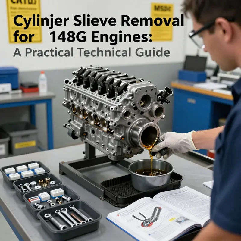
Preparation is more than a checklist; it is the mental frame that keeps unintended debris out of the engine block and keeps you anchored to the goal of a clean, accurate extraction. Begin with safety and the fundamentals of cleanliness. Ensure the engine is completely cooled and disconnected from any energy source. Drain coolant and oil so that a slip of a cloth or a stray drop cannot contaminate the bore or the new sleeve. The surrounding work area should be swept and cleaned; a loose bolt or a stray rag can become a hazard or a contaminant when the bore is exposed. With the head removed, the familiar landscape of cooling channels, coolant galleries, and the top edge of the block comes into clear view. The first contact with the workpiece is not the sleeve; it is your own preparation to respect the precision that sleeve work demands. The sleeves on the 148G, like those on many industrial diesels, are designed to be stationary in the block while the piston moves within them. That relationship—firm, supported, and aligned—makes the process possible, but it also imposes a discipline of alignment and force control that must be observed at every moment.
Access to the sleeve begins with clearing the way. The piston and connecting rod assembly must be removed from the affected bore to release the sleeve from its tight embrace with the block. This typically involves rotating the crankshaft to position the piston at bottom dead center, allowing the rod to be drawn away from the bore without binding. The removal of main bearing cap bolts and the connecting rod cap follows, done with careful restraint to avoid disturbing the crankshaft position. Once the piston is out, you gain the necessary access to the cylinder bore and sleeve interface. This is the moment when many missteps occur: thinking the sleeve is loose when the piston remains perched on a wire or the block wall has not been fully cleared of the interfering shrouds of metal and gasket material. A slow, deliberate approach here pays dividends later. Clear, single strokes with the appropriate tools are better than a flurry of activity that risks nicks on the bore surface or misalignment of the pulling instrument.
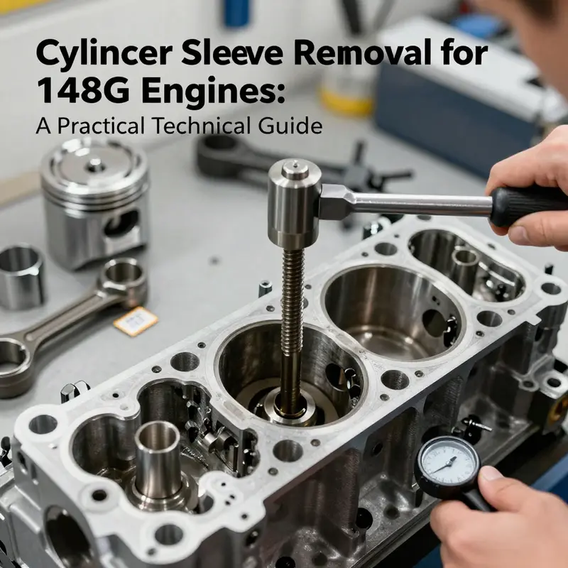
When the sleeve is finally ready to be extracted, the star tool in your hand is the cylinder sleeve puller. This device, often with a multi‑arm configuration, is designed to engage the top and bottom edges of the sleeve so that a centered, gradual pull can be applied. The importance of alignment cannot be overstated. If the puller engages off center, the risk of wall distortion increases, and a small刻 misalignment can lead to scarring or tapering of the bore. Position the puller so that its hooks or claws fit securely into the sleeve’s upper lip or the groove designed for this purpose. The central screw—usually a large threaded rod with a substantial nut—must be threaded through the frame and seated gently against the top of the sleeve. The surface at the top of the sleeve should be clean and free of burrs; any irregularity here can cause the puller to bind instead of slide, a moment that invites misalignment and uneven stress on the block wall.
The extraction itself hinges on a controlled application of force. Tighten the central bolt slowly and evenly with a socket wrench. The design of the puller is to translate the rotational motion you apply into a steady, outward pull on the sleeve. This is where patience becomes a core skill. If the sleeve resists, do not rush. A common mistake is to hammer away in an attempt to shock the sleeve free. While light tapping is sometimes used to break corrosion or the last vestiges of a tight fit, it should be applied with restraint and only as a supplementary action to the puller’s steady extraction. Excessive hammering can distort the block wall or crack the shoulder or seating surface around the bore. The sleeve may exhibit stubbornness due to a combination of rust, carbon buildup, and a slight pressed fit that has developed over many hours of service. In such cases, the gentle, methodical application of force wins over brute strength, preserving both the sleeve seat and the bore for the next phase of service.
As the sleeve begins to move, the feel through the puller’s frame changes from resistance to a more predictable pull. The operator must watch for any sign of wobble or misalignment. If the sleeve is moving, support the process with deliberate, incremental turns of the central bolt. The sleeve will gradually rise from the bore, and the final portion of its escape is often the most delicate. When the sleeve clears the bore, lift it straight out, avoiding any twisting that could extend into the bore wall or drop debris into the crankcase. The moment the sleeve is removed is the moment you breathe a small breath of relief, but the work is far from finished. The bore is now exposed to scrutiny, and the way forward depends on what you find there.
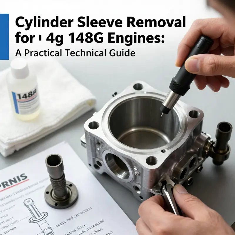
Inspection after extraction is the next critical phase. A clean bore is a prerequisite for meaningful assessment and for the life cycle of a replacement sleeve. Begin with a careful visual inspection for scoring, wear, or any signs of cracking along the cylinder wall. The presence of scoring lines or raised edges can inform you whether the bore has experienced excessive wear or if there are local hotspots that demand attention. Use a clean, lint‑free cloth and an appropriate solvent to wipe the bore and examine its walls under good light. If scoring is evident, you must determine whether honing or more extensive machining is necessary before installing a new sleeve. The condition of the bore, as much as the sleeve, governs the decision to proceed with re‑sleeving or spark a repair plan that includes honing to the proper crosshatch and finish. The removed sleeve itself should be inspected for corrosion, cracks, or deformities in its seating surfaces. A new sleeve will not remedy preexisting damage in the bore or in the block edges where the liner seats. Any irregularity here can defeat the purpose of replacing the sleeve, which is to restore a uniform cross‑sectional geometry and a consistent oil film boundary around the bore.
The discussion of tools and extraction technique would be incomplete without acknowledging the value of a well‑kept work environment and disciplined procedure. The sleeve puller, the central bolt, and even the tapping hammer all demand respect and routine maintenance. Keep tools clean, dry, and free from rust. The puller’s hooks should always be sharp, properly seated, and free of burrs that might nick the sleeve lip during engagement. A stray burr can become a point of entry for debris, or worse, a lever that skews the sleeve during extraction. Likewise, packaging and labeling removed parts—the piston, the rod assembly, and the sleeve itself—help prevent mixups and missteps during reassembly. The aim is not merely to remove a piece; it is to leave the engine in a condition where the new sleeve can be installed with confidence, where the bore is uniformly prepared, and where the future wear pattern will be predictable rather than surprising.
After you confirm the bore is suitably smooth and free of debris, you assess what comes next. The installation of a new sleeve brings into play its own set of requirements. A proper press or a hydraulic driver may be used to install the new sleeve to the correct depth and ensure it is fully seated. The surface finish around the seating area, the cleanliness of the sleeve’s outer diameter, and the integrity of any seals or anti‑fouling measures around the bore are all essential factors. The service manual for the 148G engine will specify the exact torque values, seating depths, and any lubricants or anti‑seize compounds prescribed for installation. The manual is the compass that keeps the work aligned with manufacturer expectations, and consulting it before engaging in any reassembly is prudent. It is easy to underestimate how small deviations in depth or seating can alter compression, burn quality, and coolant flow around the sleeve. The bore must be prepared to a state that allows the new sleeve to be pressed in evenly without localized stress concentrations which could lead to distortion or uneven wear.
Openly acknowledging the need for careful verification after sleeve removal means acknowledging that references matter. A trusted service bulletin or manual provides the authoritative guidance on how to approach not only the extraction, but the reinstallation, honing, and inspection that follow. The Perkins Engines family of service resources offers detailed procedures, drawings, and cautions that help align the on‑motor work with the design intent of the engine. In practice, you would cross‑check the sleeve’s orientation, the step depth, and the bore roughness against the official guidelines, ensuring that every measurement falls within the acceptable tolerance band. This is not a step you rush; it is a sequence that demands patience, double‑checking, and a willingness to pause if the bore reveals unexpected irregularities. The time you invest in careful inspection and verification pays dividends in reliability and service life for the engine.
For readers seeking a practical, illustrated walkthrough that complements the technical narrative above, there is a dedicated internal guide that outlines the sleeve removal process with visuals and stepwise cues. You can explore that resource here: How to remove engine sleeves. It offers a grounded, hands‑on perspective that reinforces the approaches described here while anchoring them in a broader set of sleeve related tasks and considerations. This internal reference underscores the theme that sleeve work, though specialized, is really about disciplined technique and consistent application of the right tools in the right sequence.
No discussion of sleeve removal would be complete without acknowledging the value of model specificity. While the general approach outlined here is broadly applicable to many engines and most configurations of the 148G family, the exact torque specifications, the depths to which sleeves must be seated, and even the recommended methods for dealing with stubborn sleeves can vary by model year, bore diameter, and factory finish. Therefore, whenever you perform this job, treat the official service manual for your exact engine as the final authority. The manual will provide critical information about torque values for the main bearing caps and rod caps, the correct sequencing of fasteners, and the precise steps required to ensure proper reassembly. In many cases, the process will also include cautions about coolant and oil system cleanliness, seal replacement, and the re‑torquing pattern that ensures the main bearing caps and cylinder block remain true to form during engine operation. Even minor deviations from the recommended procedures can lead to misalignment, which in turn can affect fuel combustion, exhaust emissions, and lubrication fidelity.
As you progress through the sleeve removal workflow, you begin to perceive the broader context of why sleeves exist in the first place: they are a solution to manage wear, heat, and material choice in a high‑stress environment. The presence of sleeves allows the engine to be repaired by replacing the worn cylindrical surface without sacrificing the integrity of the block casting itself. In a 148G, the sleeves are designed to be robust enough to withstand millions of cycles, yet accessible enough to permit refurbishment when the wear becomes unacceptable. The extraction phase is the gateway to this refurbishment. A clean bore, properly prepared to receive a new sleeve, returns the engine to a state where compression is restored, oil control is reestablished, and the finished assembly can be trusted to operate under load. The path from disassembly to reassembly is a nuanced journey that rewards careful, patient work rather than haste. It is a reminder that even seemingly small components—think of a liner’s seating edge or the precise depth of a bore—play a decisive role in the engine’s reliability and efficiency. In the end, the sleeve is not merely a part to be removed and replaced; it is a critical interface that makes possible the engine’s life after wear, letting the machine continue to perform its heavy lifting with calm efficiency.
External resources provide an authoritative frame for this practice. For a broader look at sleeve concepts and industry perspectives on how sleeves fit into the maintenance and repair of industrial engines, consult official service documentation and industry references that discuss the rationale, the common failures, and the recommended remediation steps. These resources reinforce the principle that sleeve removal should be guided by a rigorous, documented procedure rather than ad hoc methods. They also emphasize safety implications and the importance of preventing contamination and damage to the bore and surrounding structures. If you are undertaking this work, you are engaging in a craft that sits at the intersection of mechanical precision and engineering discipline. The better you understand the interplay between tool geometry, target tolerances, and material behavior under heat and pressure, the more likely you are to complete the removal with the sleeve seat ready for its successor and the engine ready for its next course of service.
For those seeking additional external context on sleeve procedures and the broader landscape of engine sleeve considerations, the Perkins service support resources offer a foundational reference point. Access to their guidance can help you align your approach with manufacturer intent and typical industry best practices: https://www.perkins.com/support. This external resource serves as a reminder that while hands‑on technique is essential, it must be complemented by the counsel of the engine’s official maintenance literature to ensure the repair life remains robust and predictable.
In sum, removing a cylinder sleeve from a 148G engine is a precise, controlled operation that starts with meticulous preparation and ends with informed reassembly. The sleeves are designed to be replaced, not torn out, and the method you employ should honor their role as a wear surface that preserves the integrity of the engine block. The disciplined use of a sleeve puller, careful engagement with the sleeve, and a steady application of force—all underpinned by a thorough post‑removal inspection—define a successful extraction. It is a process that rewards patience and accuracy and that paves the way for reliable engine performance in the years to come.
Sleeve Extraction in a 148G Engine: From Bore Preparations to Clean Reassembly
The task of removing cylinder sleeves from a 148G engine sits at the intersection of precision and patience. It is a procedure that begins long before the first tool touches metal and continues long after the sleeve is out of the bore. In engines built around heavy-duty, steel-lined cylinder blocks, sleeves are more than mere inserts; they are integral to heat management, lubrication, and structural integrity. This chapter follows a cohesive, practice-driven path that emphasizes preparation, controlled execution, and a thorough post-extraction inspection. It also underscores the importance of model-specific guidance, since even within a family of engines, the sleeve design, surrounding hardware, and torque tolerances can differ. The goal is not merely to pry a sleeve loose but to preserve the bore, ensure proper alignment for any new sleeve, and set up the engine for reliable reassembly and return to service.
Preparation and safety form the essential frame of any sleeve removal job. The engine must be completely cooled and isolated from any automatic power sources. A hot engine can contribute to thermal shock in nearby metalwork and can make fasteners behave unpredictably. Draining the coolant and the oil is not just a preventive measure against spills; it minimizes the chance of contamination while you move components. With the engine in a safe, accessible state, you should remove any obstructions that block access to the cylinder block and sleeves. The cylinder head, valve covers, and any adjacent components must be detached in a methodical sequence so you can see the sleeve’s top and bottom, along with the flange or groove that the extraction tool will engage. A clean work area around the cylinder bore is more than a convenience; it’s a practical shield against dirt and debris that can lodge in the gap between sleeve and bore, creating micro-scratches or scoring as the sleeve is drawn out.
Accessing the sleeve is a stage that often feels routine but demands exactness. In many 148G designs, the sleeve sits within the bore and must be accessed after the piston and connecting rod assembly are out of the way. The typical approach is to rotate the crankshaft so the piston is at bottom dead center (BDC). This positioning minimizes the chance that the piston will drop back into the bore or otherwise interfere with the sleeve during extraction. You then need to release the main bearing cap bolts and the connecting rod cap, carefully lifting the piston and rod assembly out of the cylinder bore. This step is not merely about freeing the piston; it is about clearing the way to expose the sleeve’s top edge for stable engagement by the extractor. During this phase, it’s prudent to check the wrist pin, gudgeon pins, and the small end of the connecting rod for any undue play or signs of wear that could affect later assembly. The more you understand the condition of adjacent components at this stage, the better prepared you will be for both removal and subsequent reassembly.
Once the sleeve is accessible, the primary extraction tool—commonly referred to as a sleeve puller or sleeve extractor—takes center stage. The puller is designed with arms that reach into grooves or flanges near the sleeve’s top and bottom. Centering is crucial here. If the puller’s arms are not seated squarely, the sleeve can tilt or bind, increasing the risk of wall damage or misalignment during extraction. After seating the tool, you tighten the central screw or threaded rod gradually and evenly. The principle behind this action is constant, controlled force rather than brute force. The sleeve should respond to even pressure by breaking its grip with the bore walls rather than tearing or scoring. A common mistake is to apply rapid or uneven torque, which can cause the sleeve to fracture, shed metal into the bore, or warp the bore itself. The operator should anticipate a degree of resistance. Patience pays here; if the sleeve resists, pause, re-check alignment, and verify that the piston assembly is fully out of the way and the bore is clean. For a sleeve to lift cleanly, you want to avoid anything that could bind at the top lip or introduce a new scratch along the bore’s surface.
As the extractor continues to engage, the sleeve will begin to emerge from the cylinder bore. The extraction process must proceed with deliberate cadence. If the sleeve starts to come free, you should maintain steady pressure and monitor for any sudden shifts or tilting that could indicate a misalignment of the tool or an obstructive feature within the bore. It is not uncommon to encounter minor resistance caused by carbon deposits or slight burrs formed by wear over time. In such cases, a careful wipe with a lint-free cloth to clear debris, followed by a light re-application of penetrating solvent if permitted by the service guidelines, can help the sleeve glide out more smoothly. Do not force the sleeve beyond the point where it clearly breaks free. Forcing can lead to unintentional wall damage, which will compromise the new sleeve’s seating or the block’s structural integrity.
After the sleeve is removed, the bore undergoes a critical inspection and cleaning phase. Visual inspection is the first tool in your kit for this step. Look for scoring, scratches, or any micro-cracks around the bore, especially near the top and bottom lands where the sleeve once interfaced with the block. Any signs of over-wear or damage should be documented and evaluated against the engine’s service history and the intended overhaul level. The next phase is cleaning. The bore must be thoroughly cleaned with appropriate solvents and lint-free cloths. It is essential to remove any oil residues, carbonized deposits, or coolant traces that could compromise the seating of a new sleeve. A clean, dry surface offers the best chance for a uniform contact between the new sleeve and the bore, which in turn ensures predictable heat transfer and lubrication behavior once the engine is back in service.
Inspecting the sleeve itself before installation is equally important. Even the most carefully designed extraction can reveal hidden defects. Check the removed sleeve for ovality, corrosion, or uneven wear along its inner surface. If the sleeve shows any defects, it should be replaced rather than re-used. This is particularly critical in engines where the sleeve’s role includes maintaining precise bore geometry for the piston ring seal and oil control. A damaged sleeve cannot simply be squeezed back into place with higher torque or a thicker gasket. The new sleeve, whether a direct replacement or an oversleeved design, must meet the same dimensional tolerances as the original. If there is any doubt about the sleeve’s condition, consult the service manual for the recommended replacement standard and the required installation procedures. In this context, model-specific guidance becomes not just helpful but essential. Different 148G variants may have distinct sleeve dimensions, seating depths, and compatibility requirements with the block’s heat-treated surface. This is where the official service documentation becomes your most reliable ally. It provides the exact tolerances, steps, torque values, and any special tools required for the exact configuration you are working with.
To connect this practical process with a broader knowledge base, consider a concise, model-agnostic reference that focuses on the sleeve removal technique rather than the engine’s exact brand. A practical guide on how to remove engine sleeves offers solid fundamentals that align with the approach described here. The guide emphasizes careful tool engagement, even pressure, and deliberate progression from top to bottom, all of which map closely to the steps needed for a 148G style bore. While that resource is not a substitute for the engine’s official service manual, it provides a useful mental model for the sequence and touchpoints you will encounter in the workshop. When you’re ready to install a new sleeve, the same discipline applies in reverse: ensure the bore is pristine, the sleeve is defect-free, and the seating surface is aligned to the block’s reference plane. The alignment matters because any misalignment can lead to uneven contact with the piston rings during the compression cycle, potentially producing blow-by, reduced sealing, or accelerated wear on the rings themselves.
The critical balance in sleeve removal and subsequent reassembly rests on the interplay between mechanical fit, surface finish, and the dream of long-term reliability. The 148G engine family, with its emphasis on robust bore design and durable sleeve materials, rewards meticulous workmanship. The bore should present a uniform, smooth inner surface after cleaning, free of gouges or residual carbon from the previous runtime, and the lip where the sleeve seats must be free of burrs or raised edges. If the bore shows minor imperfections, you may need to cure them with a proper bore polishing protocol or, in some cases, a light hone to restore the crosshatch pattern that aids ring seating. But any honing should be executed strictly following the engine’s service specifications. Inadequate or excessive honing can alter bore geometry and disturb the engine’s compression characteristics.
An implicit reality in the sleeve removal workflow is the necessity of model-specific guidance. The 148G engine family is not a single, uniform platform. Variants can differ in the mesh of components around the sleeve, the depth to which the sleeve sits within the block, and the exact method by which the sleeve is pressed or pulled into place. For this reason, the official service manual becomes the anchor for any overhaul plan. It provides precise torque sequences for the removal and installation hardware, the stipulated lubricant types and clearances, and any cautions regarding heat treatment or surface coatings on the sleeve and block. In practice, you should approach any sleeve removal with a plan that anticipates the model’s distinctive features: the exact seating depth, any heat-affected zones around the bore, and the proper alignment of the sleeve’s outer diameter with the block’s inner walls. Deviating from these specifics, even for a seemingly minor reason, can compromise the seal and lead to troublesome engine performance after reassembly. The value of model-specific documentation is evident in the way it reduces guesswork and helps preserve the integrity of the cylinder bore, the sleeve seating surface, and the linkages surrounding the assembly.
Beyond the mechanical steps, there is a mindset that underpins a successful sleeve removal. It centers on patience, discipline, and a willingness to pause and re-check at every critical juncture. The moment you feel resistance, stop and verify the alignment and seating. The moment you suspect a burr or scratch, switch to a clean cloth and appropriate solvent, then re-inspect before continuing. The simplest mistakes—tilting sleeves, over-tightening an extractor, or neglecting a thorough bore clean—are the ones most likely to result in longer downtime and costly reworks. In the end, sleeve removal is as much about preserving future service life as it is about the immediate task of freeing the sleeve. The engine’s longevity hinges on the accuracy of every subsequent step: the seating of a new sleeve, the restoration of the cylinder’s cross-hatch surface, and the fidelity of the mating surfaces between the block, the sleeve, and the head gasket. When these elements align, the engine can enter its next phase with the confidence that the bore, the sleeve, and the surrounding components will perform in concert for many hours of service.
For practitioners who value a grounded, methodical approach, the key takeaway is clear: reference your engine’s official service manual for the exact torque sequences, seating depths, lubrication requirements, and recommended tools. Even when the general workflow seems straightforward, the subtle differences between variants can determine whether sleeves seal properly, whether rings seat correctly, and how reliably the engine will perform after reassembly. The path from bore preparation to clean reassembly is littered with potentially small but consequential decisions. By treating each step as a discrete check—an opportunity to confirm alignment, verify cleanliness, and ensure no debris or burr remains—you can minimize the risk of introducing a fault that only becomes apparent after the engine is back in service.
As you prepare to install a new sleeve or re-sleeve a block, remember that the benchmarks you established during removal—careful cleaning, meticulous inspection, and strict adherence to model-specific tolerances—will guide the entire process. A well-executed sleeve removal programme not only returns the engine to service but also lays the groundwork for predictable performance, efficient lubrication, and durable seal integrity throughout the engine’s working life. While the technical heart of the task lies in the physical act of extracting and seating sleeves, the real craftsmanship resides in the disciplined attention to detail that begins with preparation and ends with a clean, well-dressed bore ready for reassembly. In practice, the combination of careful preparation, measured extraction, thorough inspection, and strict adherence to model-specific guidelines is what turns a challenging mechanical procedure into a repeatable, reliable maintenance operation. For anyone performing this work, the guiding principle is simple: precision at every step lowers the risk of future issues and maximizes the engine’s return to service with confidence.
External reference: For model-specific service information and precise torque specifications that apply to the exact configuration you are working with, consult an official service documentation resource such as the Technical Information System. This kind of reference is essential when the goal is to ensure that the bore geometry, sleeve seating, and related torque specifications align with the engine’s design intent. You can explore model-specific repair guides and diagrams through official technical information portals, which provide diagrams and procedures that reflect the latest maintenance recommendations. External resource: https://www.bmwusa.com/technical-information
Final thoughts
Removing cylinder sleeves from a 148G engine demands disciplined preparation, the correct extractor technique, and a thorough inspection afterwards. First, secure the engine, drain fluids, label and organize parts, and follow safety protocols so the block and technicians remain protected. Second, use a dedicated sleeve puller, center the tool, apply even pressure, and remove the sleeve slowly while monitoring alignment to avoid scoring the bore. Finally, inspect the block with a borescope, clean with approved solvents, and consult the model-specific service manual for torque values, sleeve orientation, and replacement specifications. For motorcycle and auto owners, parts distributors, and repair shops, adherence to these steps reduces rework risk and preserves engine life; when in doubt, consult the official Perkins service documentation or send the block to a certified machine shop.