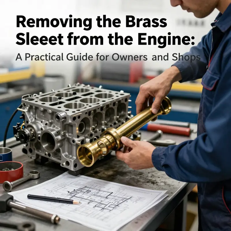
Removing the brass sleeve from the engine is a precision task that sits at the intersection of metalworking, engine design, and proper maintenance. Brass sleeves, also called bushings or insert sleeves, provide steadfast alignment and wear resistance in various engine components. While sleeves are small, their removal, if done incorrectly, can trigger costly damage to the bore, shafts, or surrounding housings. This article speaks to motorcycle and auto owners, auto parts distributors and wholesalers, and repair shops, offering a practical framework to approach brass sleeve removal with confidence. It emphasizes scope and definitions, how to identify the sleeve and its mates, the right tools and methods, and the safety and documentation practices that protect both people and parts. Each of the four chapters builds toward a reliable workflow: first establish what the sleeve is and where it sits; second, recognize the bearing surfaces and associated components and the risks of deformation; third, survey the tools, removal strategies, and procedure logic; and fourth, align safety, standards, and professional guidance with the engine’s service manual. The result is a holistic understanding that helps owners and shops decide when to proceed, when to seek a specialist, and how to preserve engine integrity throughout the process.
From Fit to Freedom: Navigating the Removal of Brass Sleeves in Engine Assemblies
The phrase brass sleeve in the context of an engine invites immediate questions. In many repair manuals and everyday machinist chatter, the term can be misunderstood or borrowed from other domains where brass sleeves or bushings are common. In engines, however, sleeves—or cylinder liners—are typically steel, cast iron, or sometimes alloy sleeves integrated into the block or head. A brass sleeve, if it appears at all in an engine assembly, is far less common and usually sits in a niche role such as a wear-resistant insert in a surrounding housing or as a bushing in accessory components. This chapter does not pretend to provide a universal, model-by-model procedure. Instead, it offers a grounded way to think about the challenge, the kinds of fit you might encounter, and the cautions that come with attempting to remove a brass sleeve from an engine. The reality is that such removals are model-specific and often require the guidance of official service documentation. The knowledge base you start with highlights a crucial point: many references to “brass sleeves” concern fasteners and bushings used in cabinetry and general machinery, not an engine’s cylinder bore. When the sleeve you are facing is truly part of the engine’s internal structure, its removal is not a casual, do-it-yourself task. It is a job that demands exacting precision, correct tooling, and a clear plan to avoid collateral damage to the bore, coolant passages, or surrounding components. This is why the first, most important step is to identify what exactly your sleeve is, how it is engaged with the housing, and whether it is an interchangeable insert or a hard-wearing, integral part of the block. When you pause at this interpretation, you lay the groundwork for a responsible approach rather than diving into a trial-and-error sequence that could compromise the engine. In practice, most readers will begin with the sober realization that a brass sleeve, if present inside an engine, is governed by the rules of official service literature. The removal procedure will vary by engine family, bore size, sleeve material, and whether the sleeve is a press-fit, interference-fit, or a slip-in insert designed to be serviced only under controlled conditions. The absence of a universal method is not a flaw; it is a reflection of the engine’s individual design and the precision required to preserve performance after reassembly. For those who want a targeted path, there is a resource that addresses the general theme of engine sleeves and offers a practical starting point: how to remove engine sleeves. This guide can be accessed through the dedicated article at its URL, which provides context and cautions that align with the concerns described here: how to remove engine sleeves. The link is not a substitute for the manufacturer’s service manual, but it helps frame the approach you will take when you consult the official documentation. The core idea across all models is that sleeves are not regular fasteners; they are engineered interfaces between moving parts, and their removal must respect the integrity of the bore, the surrounding seats, and the mating components. Once you have established that your brass sleeve is indeed a removable insert rather than a fixed block feature, you begin to map out a plan that prioritizes control, alignment, and protection of the cylinder walls and oil passages that feed the engine’s internals. The best starting point remains identification and measurement. A sleeve that is press-fit or interference-fit will demand different preconditioning and extraction methods than a sleeve that simply slides out with careful support. The first practical move is to verify the sleeve’s exact fit condition: is there any visible evidence of an interference nature, such as a narrow shadow around the sleeve, a slightly raised edge, or resistance when attempting to slide it with a calibrated hand tool? Is the sleeve hexagonal or round in cross-section after any wear? These observations help determine whether heat, cooling, or mechanical extraction is appropriate. The next step is to consult the service manual for the engine. A manual will specify the acceptable tools, the required tolerances, and the sequence for any sleeve replacement. It is not unusual for an engine to require an external press, a calibrated puller, or a combination of heat and mechanical leverage to free a sleeve without misaligning the bore. In some cases, manufacturers instruct the technician to prepare the bore for re-sleeving or to replace the block entirely if the bore has been compromised. These are not cosmetic repairs; they are structural decisions, because a misaligned or damaged bore can lead to low oil pressure, loss of compression, and eventual engine failure. If the sleeve location sits behind a complex network of oil passages, coolant galleries, or threaded tie-ins for bearings, the removal becomes even more delicate. The risk of collateral damage rises with the number of critical features adjacent to the sleeve. This is exactly why the advice from the knowledge base emphasizes specialized tools such as pullers, hydraulic presses, or heating techniques. A brass sleeve inside an engine is not something you improvise with a hammer and punch. Even with the correct tools, the operation must be controlled. The use of heat must be carefully managed to avoid warping the bore or compromising adjacent materials. The application of heat to the sleeve or the housing should be measured, and often the components must be clamped and supported to prevent distortion once the sleeve begins to move. A backer block or a sacrificial mandrel may be used to preserve the bore as the sleeve yields to the extraction forces. Penetrating oils or drying agents can help reduce the friction at the interface, but they are not substitutes for the mechanical and thermal control that the job demands. It is also essential to consider the orientation of the sleeve. Some sleeves are designed to be removed in a particular direction or with a defined alignment to prevent damage to the bore’s finish. Marking the sleeve and the bore with a light, durable indicator before disassembly helps ensure that reassembly occurs with the sleeve oriented correctly and the bore surface preserved. The reassembly stage is just as important as removal. Once the sleeve has been freed, the bearing surface and the bore must be cleaned and inspected for any scoring, scratches, or micro-peening that would imperil the seal or the compression. The decision to re-sleeve or re-bore depends on the extent of wear, the remaining material thickness, and the engine’s overall design limits. In some engines, the sleeve is replaceable and the bore can be re-lubricated and re-sized with an appropriate insert, while in others, the block must be re-sleeved or bored to accept a larger sleeve or a different cylinder liner. The overarching principle is to preserve concentricity and surface finish. Any deviation from true circularity or a rough surface on the bore can cause piston ring wear, oil consumption, and reduced compression. Therefore, every stage of the process—from extraction through inspection to iteration of the seating—should be performed with careful measurement and verification. The absence of a universal method also underscores the value of professional support when a brass sleeve is involved in an engine. If the sleeve is part of a critical bearing or near a fluid passage, the risk calculus shifts toward using specialized services. Do not underestimate the value of an accurate, model-specific procedure. In the end, the decision to attempt removal, the choice of tools, and the method of extraction all reflect a balance between the sleeve’s role, the engine’s design, and the technician’s adherence to manufacturer guidance. The aim is to reach a state where the engine remains trustworthy after reassembly, not to achieve a quick cosmetic result. For readers seeking a concise, model-agnostic starting point, the reminder remains: know what you are dealing with, use the right tool for the right task, and consult the official service documentation before you perform any removal. If you want to explore a more targeted discussion or a step-by-step approach specific to engine sleeves, the linked guide offers a practical frame and cautions that align with the themes discussed here. The broader takeaway is that sleeve removal is a precision operation, not a routine maintenance task, and it benefits from careful planning, proper tooling, and disciplined execution. External safety considerations include ensuring the engine is cool, disconnecting the battery to prevent accidental sparks, and maintaining a clean environment to avoid introducing debris into the oil and cooling systems. These precautions, while seemingly mundane, are essential to avoid cascading damage once the sleeve is removed or during subsequent reassembly. Finally, it is worth noting that the terminology surrounding sleeves can vary between industries. A brass sleeve in one context might simply describe a brass-lined or brass-coated seat that reduces wear. In the engine world, however, you must verify whether the component is an insert or an integral bore feature. If you are unsure, treat the situation as potentially non-servicable in a home shop and seek professional guidance. This approach respects both the equipment and the skill set required to perform such a precise operation. For readers who want to familiarize themselves with the broader topic of sleeves in engine design and servicing, consider additional reading on sleeves and their function within engine blocks and assemblies. You can also explore the related, model-specific guidance in the linked resource above to gain a clearer sense of how professionals approach removal, measurement, and reassembly. As you navigate this topic, remember that the goal is to maintain or restore reliability, not to skirt around the core engineering challenges that sleeves present. External resource: https://en.wikipedia.org/wiki/Bearing_(mechanical).
Tracing the Brass Sleeve in the Engine: Identification, Risks, and Safe Removal
Brass sleeves in engines occupy a niche but critical role. They are not a universal feature in every powerplant, yet in certain designs they function as bearing inserts, bushings, or wear-surfaces that accommodate moving parts with close tolerances. When you encounter a brass sleeve in an engine, you are dealing with a component whose removal demands respect for the surrounding architecture. The knowledge you need to approach it is not merely a matter of following a unwinding checklist; it requires a mindset that blends identification, verification, and precise mechanical technique. The temptation to treat a sleeve like a simple bolt or spacer quickly fades when you map out the way the sleeve interacts with the crankcase, the piston, and the lubrication system. This chapter does not pretend to replace a manufacturer’s service manual. Instead, it builds a cohesive understanding of how to identify the sleeve, why removal is a delicate operation, and how to plan a safe procedure that minimizes damage to the engine block, bearing surfaces, or adjacent components.
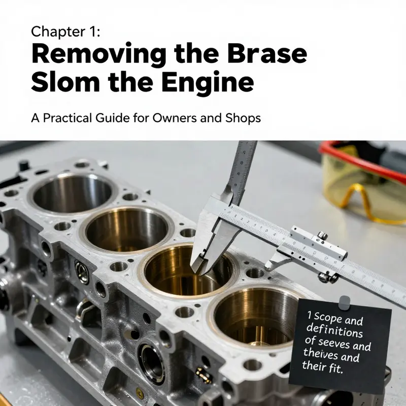
First, identification is the foundation. A brass sleeve may sit in a cylinder liner, a main bearing housing, or a dedicated bushing seat in a moving assembly. Its brass composition is not just about material identity; it signals a set of design expectations: low friction under sliding contact, compatibility with lubrication regimes, and a defined interference fit or press-fit that keeps the sleeve in place under thermal and mechanical loads. The immediate surroundings—oil galleries, coolant passages, and the interfaces with the crankshaft, camshaft, or connecting rods—must be understood before any physical action begins. You will want to verify whether the sleeve is a wet-sleeve or a dry-sleeve arrangement, since the moisture and oil environment around a wet sleeve can affect both removal strategy and the risk of bore damage. In engines that use brass bushings as alignment guides or pilot sleeves, the sleeve’s location may be obscured by bolt patterns, flanges, or timing components. That is where meticulous visual inspection comes into play. You should look for features that hint at how the sleeve is secured: a press-fit shoulder at the bore edge, a step in the bore that defines a seating plane, a retaining ring groove, or a thin-walled interference section that invites careful heat application. The process of identification is not merely about “finding brass.” It is about confirming the purpose of the sleeve within the engine’s life cycle. The risk of misidentifying a part as a brass sleeve when it is actually a hardened bronze insert or a steel bushing is not trivial. The wrong removal approach can lead to unintended metal deformation, micro-cracks in the housing, or loss of bore roundness. The practical course is to cross-check the visual clue with a service manual or a trusted technical diagram that specifies the sleeve type, its seating method, and the permissible methods for removal or replacement.
Next comes the responsibility of recognizing the risks. The road to safe removal is paved with awareness of several interlocking hazards. One of the most common and silent risks is the potential for misalignment during extraction. A sleeve that is not perfectly coaxial with the bore can seize when a pulling force is applied, leading to scoring on the cylinder wall or chatter that distorts the seating surface. Even a seemingly minor misalignment can cause the sleeve to walk and cause the bore to become oval. Temperature is another influential factor. Brass expands as it heats, and the engine block expands as it reaches operating temperature. The removal task often applies a targeted heat to the sleeve or the surrounding area to create a differential that eases extraction. However, heating the wrong component or applying heat too aggressively can warp the bore, soften nearby alloys, or alter the surface finish of the cylinder. The safe course is measured, localized heating—ideally with a source that can be controlled precisely and monitored for the surface temperature—while shielding adjacent components from heat soak.
The internal geometry matters as well. A sleeve with a tight press fit that relies on an interference around its outer circumference will demand a different removal approach than a sleeve retained by a retaining ring or by a shoulder. If there is a shoulder, it provides a natural stopping point to avoid driving the sleeve deeper into the block. In contrast, if the sleeve is secured by a ring or a locking feature, you must first release that constraint with an appropriate tool and pressure before attempting extraction. The tool path is critical; a misapplied force can shear a non-sleeve portion of the assembly or deform the bore edge. Because brass is relatively soft compared with steel or cast iron, excessive force can lead to localized galling or smearing, potentially contaminating oil passages or lodging brass fragments into the lubricant system. The risk cascade does not stop there. Debris from the sleeve, should it shed during removal, can migrate into the piston ring lands or into crucial lubrication channels. That breach can escalate into scoring, oil consumption, or lubrication starvation. In short, the removal process carries a spectrum of harm that extends beyond the sleeve itself.
With identification and risk awareness in place, the practical strategy unfolds in careful, methodical steps. The best practice begins with a clean work environment and a clear plan that prioritizes preserving bore roundness and surface integrity. Before any tool touches the sleeve, you should document the bore’s condition. A bore gauge or a high-precision dial indicator can establish whether the bore is within tolerance and whether the sleeve sits true to axis. Any preexisting waviness or eccentricity in the bore will magnify during removal. Once the baseline is established, you move to determine the most appropriate removal method. If the sleeve is a press-fit, the removal technique often relies on a controlled combination of heat and a sleeve extraction tool that can apply even pressure around the circumference. If the sleeve is retained by a ring, guides, or shoulders, you may need to first disengage the restraint with a precision punch, or remove a retaining element using a puller designed for small, delicate parts. In engines where space is tight, a remote or internal puller that can access the sleeve through access ports can minimize the risk of collateral damage. Should the sleeve be a dry bushing in a tight, non-hydrocarbon environment, a mechanical extraction approach with a slide hammer or a calibrated press becomes essential. The guiding principle is to apply force uniformly and to avoid concentrating pressure on any one point along the sleeve’s outer surface. Uniformity is not a luxury; it is a defense against distortion that can be expensive to repair.
As a practical matter, it is wise to consult and follow a specialized sleeve-removal technique rather than improvising with generic extraction tools. In engine work, there are many subtle variables that can swing an operation from feasible to ruinous. The sleeves in particular sit at the intersection of structural integrity and dynamic motion; they must endure not only static loads but the cyclic stresses of engine operation. A measured approach, stepping through each stage with checks for concentricity and surface condition, reduces the likelihood of introducing hidden damage that becomes apparent only after reassembly. If you have access to a dedicated sleeve-removal tool, use it in conjunction with the appropriate fixtures and guides to maintain steady alignment during withdrawal. If such a tool is not available, the alternative is to construct a safeguarding setup that distributes force evenly and permits incremental travel of the sleeve—always with the aim of maintaining bore integrity and avoiding any gouges or burrs that would seed future wear. The emphasis on control cannot be overstated: even a small error in height, angle, or pressure can cascade into costly repairs later.
The question of reassembly follows the removal, and it is not a simple re-installation. In many cases, removing a brass sleeve necessitates evaluating whether the bore remains within specification. If the bore is oversized or the original sleeve has worn unevenly, the proper remedy may be to bore or hone the cylinder to a standard oversize and install a new sleeve that matches the updated bore. This is a decision that should be made in concert with the service documentation for the engine and, ideally, after the sleeve is out and measured against the manufacturer’s tolerances. Surface finish and roundness must be validated post-removal, because even if the sleeve is successfully extracted, any damage to the cylinder wall would undermine compression, oil sealing, and longevity. In practice, you may find it prudent to replace the sleeve with a new insert that is designed to fit the revised bore and to re-check the alignment with thrust surfaces and oil seals. The lubrication regime is also essential to consider. Brass, while compatible with many oil formulations, can pick up wear debris differently than steel or aluminum, and any residual brass particles in the oil passages can alter lubrication film formation. During reassembly, you should perform a thorough cleanliness protocol: wipe down the bore, flush oil channels where feasible, and confirm there is no debris capable of migrating into the rings or piston lands. Finally, verify that the sleeve’s installation has not altered the engines’ critical clearances, including piston-to-bore, ring end-gap, and any hydraulic clearance in the lubrication system. A well-executed sleeve replacement should restore the engine’s intended fit and leave you with a bore surface that can sustain the next cycles of operation without contributing to early wear.
It is worth returning to the broader context of guidance for this task. The reality is that engine-specific procedures for removing brass sleeves vary widely across models and configurations. While some engines may benefit from a straightforward press-out with appropriately supported fixtures, others demand a more nuanced approach that engages heat management, simultaneous axial and radial support, and careful control of the sequence in which any retaining features are released. Because safety, accuracy, and long-term reliability hinge on these details, the prudent path is to anchor the operation in the manufacturer’s service documentation or in the instructions of a qualified technician who has performed this exact task on the same engine family. If you are seeking a practical overview of the removal concept, you can consult general guides that address how to remove engine sleeves and related components. For readers who want a concise starting point, see this resource: how to remove engine sleeves.
As this exploration shows, the removal of a brass sleeve is not a generic, one-size-fits-all task. It requires a disciplined, engine-specific plan, a clean workspace, and the right combination of tools that can apply force evenly and controllably. It also requires an understanding that the sleeve’s purpose—be it bearing surface, alignment aid, or wear surface—guides not just the removal method but the subsequent choices about bore treatment and sleeve replacement. The overarching message is clear: do not proceed by guesswork. The correct approach aligns with the engine’s design intent, leverages careful measurement, and uses controlled techniques to minimize risk to the block and to the lubrication system.
For readers who want to delve deeper into the risks and governance surrounding component identification and safety, an external reference offers broad, standardized insights into quality assurance and certification services. This perspective underscores the importance of validated processes when performing any restoration or repair that touches critical engine life. External reference: https://www.sgs.com/en/industries/manufacturing/quality-assurance-and-certification-services
Extracting the Brass Sleeve: A Patient, Tool-Driven Path Through Engine Sleeve Removal

Removing a brass sleeve from an engine is a task that sits at the intersection of precision and patience. In many engines, a brass sleeve acts as a bearing insert or a bushing that guides or supports a moving part, from a shaft to a crank or valve mechanism. Brass is chosen for its machinability and its favorable tribological properties when paired with certain metals and lubricants. But the very qualities that make brass useful also make sleeve removal a delicate operation. These sleeves are typically installed with a tight fit—often an interference or press fit—so they stay centered and resist movement under load. Because of that, a careful, methodical approach is essential to avoid gouging the bore, distorting the housing, or compromising adjacent components. This chapter follows a practical, engine-agnostic path that emphasizes assessment, controlled force, and correct tooling rather than brute force.
Begin with a calm assessment. Identify exactly where the brass sleeve resides and what it supports. Is it a mid-block bushing supporting a shaft? A governor or timing element housed in a brass insert? Or a sleeve that protects a journal or a gear shaft at the edge of a housing? The answer will shape the removal strategy. You will likely encounter three overarching realities: the sleeve’s fit type, the surrounding geometry, and the risks to the bore and mating parts. If the sleeve is seated firmly and there is little room for movement, you are dealing with an interference fit that requires attention to thermal expansion and support. If it is a slip-fit sleeve in a softer aluminum or cast-iron housing, the approach can be gentler but still demands even, axial force and careful alignment. The general rule is to work with the sleeve’s axis true, minimize cocking or tilting, and use tools that apply steady, controlled pressure rather than sudden prying.
A decisive first step is to confirm material and geometry, not just the sleeve’s position. Brass sleeves can be part of a larger assembly where lubrication channels or cooling passages interact with the insert. If you see any signs of galling, scoring, or heat discoloration on the sleeve itself, you must proceed with extra caution. The brass surface, while forgiving under lubrication, can be damaged by sharp tools or aggressive pushes that transfer to the bore wall. Take the time to clean around the sleeve, remove any oil, and inspect for rust or corrosion on the housing faces. A quick measurement of the bore diameter and the sleeve’s outer diameter—before you attempt removal—helps you select the right tool and the correct amount of force. In many cases, this is where a professional manual or a service bulletin for the specific engine family becomes invaluable, because the exact tolerances and recommended methods vary from one design to another.
When the sleeve must come out, the toolbox options multiply. A bearing puller, a small hydraulic press, or a drift used with patient, aligned force can all get the job done, provided they are used correctly. A puller that captures the sleeve evenly along its circumference is ideal because it minimizes cocking. If space is limited, you may need a compact puller or a slide hammer that can engage a suitable counterface on the sleeve or its surrounding rim. In many engine contexts, you will not be able to press the sleeve out from the cover side without first removing surrounding hardware, such as the shaft, fasteners, or timing components that obstruct access. That preparatory work is not merely mechanical; it ensures the sleeve can be driven out along its axis without bending anything or transferring force to nearby journals.
Heating is a time-honored ally in sleeve removal, but it must be used with discipline. The idea is to heat the housing around the sleeve enough to cause a slight expansion of the bore while avoiding overheating the brass itself. A controlled heat source—applied to the housing faces perpendicular to the sleeve’s axis—can reduce the friction holding the sleeve in place. The brass sleeve should not be heated directly; brass conducts heat quickly, and direct heat can cause uneven expansion that invites distortion. The surrounding cast iron or aluminum tends to respond predictably to heat, especially when combined with a measured application of lubricant or penetrating oil to the sleeve’s interface. It is critical to maintain a consistent temperature and to monitor the sleeve’s resistance to movement as the housing expands. If the component is a multi-piece assembly, ensure that other interfaces are not being stressed during the process.
Penetrating oil, though often discussed in hushed tones, has a tangible role here. A light application around the sleeve’s visible edge can help lubricate the interface once force is applied. Allow time for the oil to wick into the joint before applying final pressure. Do not rush; the goal is to reduce friction without forcing excessive loads that could crack the housing or fragment the sleeve. If the sleeve refuses to budge after heat and oil have done their work, recheck alignment and consider a slightly longer approach with a different tool—sometimes a longer travel with the same axial force is more effective than a short, aggressive move.
The actual removal must be aligned with the sleeve’s axis to preserve concentricity. A common misstep is applying force off-axis, which can tilt the sleeve and ruin the bore or press the sleeve into an unfavorable angle that will cause future seating problems. For this reason, many technicians favor a dedicated support fixture or a jig that clamps the housing without marring the exterior while the sleeve is being displaced. If a jig is unavailable, fashion a temporary solution that places the body of the engine in a stable position and uses a solid backing behind the sleeve to receive the force. The backing material should be softer than the housing and free of burrs that might catch on edges as the sleeve exits. A careful, progressive sequence—small, repeated moves rather than one large push—helps maintain control and reduces the chance that the bore will be damaged.
As you approach the moment of extraction, think about the consequences of what comes next. A brass sleeve removal can reveal a worn bore, a misaligned journal, or an affected lubrication path that requires immediate attention. After the sleeve is out, you should carefully inspect the bore for taper, scoring, or ovality. A worn or damaged bore might necessitate re-boring and sleeving, or, in some designs, a replacement sleeve with the correct interference fit. In the event of any damage, you must measure and document the bore size, the sleeve wall thickness, and the facing surfaces to guide the next steps. It is worth repeating that engine-specific manuals often prescribe the exact reaming, honing, or sleeving sequence required for your model. When in doubt, consult the service manual for the engine family you are working on; the model-specific tolerances and steps can differ markedly from one engine to another.
In practice, a successful sleeve removal blends preparation, controlled heating, precise axial force, and careful observation. The key is that no single tactic carries all the risk away; rather, the combination—aligned force, proper tools, and surface protection—reduces damage while enabling a clean extraction. If you want a concise, model-specific walkthrough that aligns with the general approach outlined here, you can consult how-to resources that walk through engine sleeve procedures in practical terms. For a practical, model-specific walkthrough, see this guide: how to remove engine sleeves.
Beyond the mechanical steps, there is a broader discipline to sleeve removal that mirrors the mindset of any careful machine repair. Before you begin, you should prepare a clean workspace, gather the correct sized puller or pressing tools, and have a plan that includes backup steps if the first attempt fails. Document the setup with photos or sketches. This habit not only helps you retrace your steps later but also supports quality control if the project scales into a professional repair or a rebuild. Once the sleeve is removed, you will be faced with the question of what the next surface will require. Some engines call for re-sleeving or re-boring with a new sleeve to restore the original bore diameter and alignment. Others may simply need the bore to be cleaned and inspected for straightness and roundness, followed by proper lubrication pathways restored. Either way, the transition from removal to reassembly is where the art and science of engine restoration collide. The sleeve itself is not just a part to be discarded; it is a clue to the engine’s history—the fit, the wear, and the conditions under which the machine has operated.
The process may feel slow, but there is a value in deliberate technique. You are not just extracting a component; you are preserving the integrity of the housing, maintaining alignment for future operation, and setting the stage for a reliable reassembly. Engine sleeves, including brass variants, often have to function in a demanding thermal and mechanical cycle. The more you understand their role within the specific engine architecture, the more confident you will be in choosing the right removal method and in evaluating the condition of the surrounding surfaces after extraction. If you are new to this kind of task, take the approach of a curious diagnostician: confirm fit, prepare for controlled release, and verify outcomes with careful measurement. In the end, the sleeves tell a story about how the engine wore, how it was maintained, and what the next steps must be to restore performance.
Ultimately, sleeve removal is a gateway to a broader set of restoration choices. It is about ensuring that the engine’s core geometry remains true, that lubricant channels remain accessible, and that the new or repaired interface will perform predictably under load. The principle of using appropriate tools, applying heat and force judiciously, and protecting critical surfaces lies at the heart of any successful extraction. For readers pursuing a deeper, procedure-oriented reference, the linked guide provides a practical blueprint that aligns with the general principles described here. It is one thing to know the theory; it is another to apply it with the kind of care that prevents collateral damage while delivering a clean, reliable result. As you move from removal to any subsequent machining or sleeving, keep a steady pace and a clear plan. The outcome will be a bore that is true, a sleeve that seats properly under its new constraints, and a rebuilt engine with its performance restored to its designed tolerance.
External reference: https://en.wikipedia.org/wiki/Bearing_(mechanical)
The Brass Sleeve Challenge: Safe Removal, Manufacturer Manuals, and Professional Guidance
Removing a brass sleeve from an engine is a task that sits at the boundary between careful craftsmanship and precise engineering. It rarely appears in quick-reference guides, yet it matters for longevity and reliability when sleeves are used as bushings or liners in a cylinder block. The brass sleeve, often pressed into a housing or cylinder wall, serves to provide a wear-resistant surface, reduce friction, and maintain alignment between moving parts. Because its fit can be an interference fit or a closely matched slip fit, the approach to removal must be as methodical as the original installation. A chapter like this connects the practical realities of disassembly with the broader discipline of engine maintenance, anchoring every action in safety, proper tools, and the guidance that comes from manufacturer manuals and professional experience.
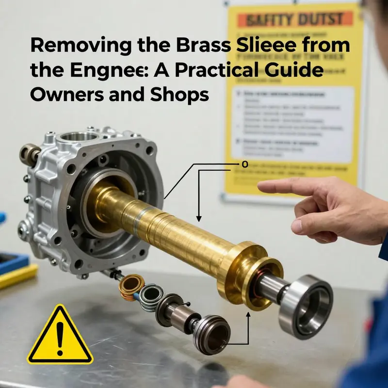
The starting point is safety and preparation. Engine work demands you treat heat, fluids, and rotating assemblies with respect for potential hazards. Before any tool touches the brass sleeve, the engine should be cool, and all power sources disconnected. Battery ground is removed to prevent accidental cranking, and any pressurized systems—coolant, oil, or fuel lines—need to be safely depressurized or isolated. A clear workstation is essential. This is not a task for improvisation or rushed heuristic methods. The sleeve’s removal, especially when it is brass or brass-like alloy, can generate metallic fragments and fine dust. Eye protection, gloves, and a good hearing shield if you’re using power tools or hydraulic presses are minimum requirements.
Once the fundamental safety steps are satisfied, the practical work begins with access. The brass sleeve is rarely exposed in the open; it sits behind the cylinder head or behind a structural wall of the engine block. Access often means removing the cylinder head and possibly related components, such as the timing cover, valve train, and surrounding shrouding, to reveal the sleeve structure. In engines that rely on cylinder liners, the sleeve sits in a bore and is designed to be removed without disturbing the crankshaft or pistons, but that depends on the exact architecture. The work must be guided by the manufacturer’s service manual for the specific engine model. These manuals lay out, in exact terms, which parts must come off first, the sequence of steps, and any critical clearances or brackets that must be preserved during removal.
With access achieved, the next decision point concerns identification. Brass sleeves are not universal in every engine, but when present, they tend to serve as the wear surface for the piston and ring assembly, or as a liner that accepts certain bearings or bushings. Inspect the sleeve’s condition: is it free to move with a light tapping, or is it bonded to the surrounding block? Does the bore look uniformly worn, or are there marks indicating a localized hot spot or accelerated wear? The method chosen to free the sleeve hinges on its fit. If the sleeve is an interference-fit insert, heat can be used to expand the surrounding metal slightly, allowing the sleeve to be coaxed out with minimal force. If the sleeve relies on a press-fit, a mechanical puller—often a purpose-built sleeve or liner puller—is the safer route. In either case, the principle remains the same: apply force evenly and avoid concentrated impact that could crack the block, warp the bore, or gouge the cylinder wall.
This is where knowledge and technique intersect. The literature and factory practices emphasize two core ideas: use the correct tool and apply force uniformly. The two different sleeve puller tools you might encounter are designed to work from opposite directions or to engage the sleeve at different points. One tool may grasp the sleeve from the outside and pull it straight out, while another may work from the inside or use a clamp-in approach to spread the load. The goal is to avoid marking the bore, to minimize heat transfer to adjacent components, and to protect the surrounding metal from tearing or distortion. When you’re applying a pulling force, keep the workpiece well-supported. A chisel-edge strike or a hammer blow is not an acceptable method for a sleeve that must come out cleanly. Instead, you should rely on a controlled, incremental pull, often with a release between attempts to ensure that the sleeve remains aligned with the bore and does not tilt or bind.
The role of heat in removal deserves careful attention. If heat is chosen as part of the procedure, it must be applied with restraint and accuracy. A heat source with controlled, even distribution—such as a calibrated induction heater or a hot plate designed for engine work—can encourage the sleeve to yield without risking distortion of the bore or nearby components. The risk of thermal damage is real: excessive heat can anneal the metal around the bore, change clearances, or weaken the block’s structure. Heat should never be applied haphazardly or in the presence of flammable fluids. A thin protective sleeve or shielding material can help preserve the surface finish around the bore while you work the puller into position.
When the sleeve starts to break free, progress should be steady and monitored. You may feel the sleeve move in small increments as the interference fit breaks or the press-fit yields. At this stage, it’s prudent to pause and recheck alignment. A slight misalignment can convert a controlled removal into a misaligned pull, which risks scarring the bore, bending the block, or tearing the sleeve’s edge. Periodic checks with a straightedge or a light gauge across the bore are prudent if you have the experience to do so. The operator must also control debris: when the sleeve begins to separate, small metal fragments can fall into the crankcase or onto the piston surfaces. A clean, well-lit work area, plus a magnet or a small debris tray, helps maintain a clean environment during extraction.
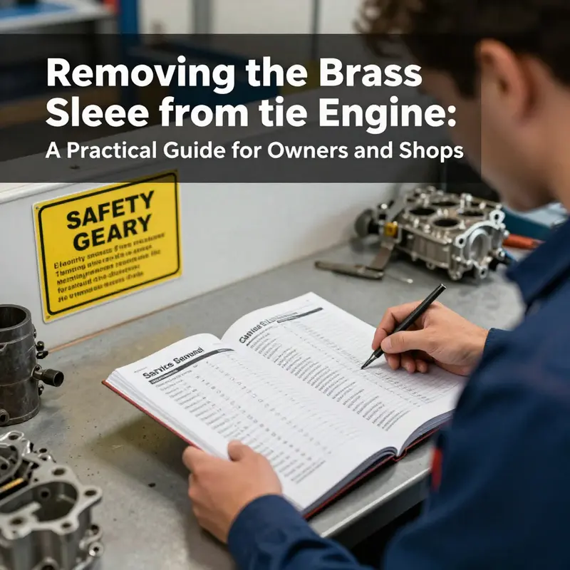
The chapter’s guiding principle—consult the official service manual for the engine model you are working on—cannot be overstated. The manual provides the exact tool list, sequence, and torque specs for reassembly. It may specify whether a sleeve removal requires loosening adjacent components first, whether any dowel pins or keys must be preserved, and how to handle the bore’s finish after sleeve removal. The manufacturer’s manual is the most reliable source for the delicate points that general guidance cannot capture. In practice, many technicians will cross-check several sources: the service manual for the engine, a reputable cylinder liner removal guide, and professional experience gained on similar engines. The knowledge base you’d reference in a project like this often highlights the cylinder liner removal guide as the closest relative to brass sleeves, because cylinder liners frequently employ copper-based materials in the same family as brass when used as liners or bushings. That guide informs the technician about safe heating, even load distribution, and the importance of avoiding score marks on the bore. It’s a reminder that the removal process is as much about preserving future viability as it is about extracting a part.
As the sleeve begins to emerge, there is another part of the practice to honor: cleanliness and inspection. Once the brass sleeve is out, the bore and surrounding surfaces should be inspected for any residual material, scoring, or micro-cracks. If the bore shows any wear, you may need to plan for re-boring and sleeving or re-sleeving, depending on the engine’s design and the manufacturer’s guidance. Even if the sleeve is removed without visible damage, the surface finish must be reestablished to ensure a proper fit for any replacement sleeve. Debris must be completely cleared before you proceed with reassembly. The reinstallation process, guided by the service manual, will usually specify the correct orientation of any liner or sleeve, the use of lubricants or assembly compounds, and the press or alignment force required to seat a new sleeve without introducing warpage.
The narrative here also reflects a broader truth: while the brass sleeve removal can be framed as a technical procedure, it sits inside a framework of professional practice. If you are performing this work as part of a larger rebuild, you may be balancing multiple priorities—budget, downtime, the availability of replacement parts, and the risk of damage to valuable engine components. The manual’s guidance, then, becomes even more valuable because it provides a tested path through these competing concerns. It helps avoid improvisation that could lead to costly errors. For many technicians, the path of least risk is to consult the official service manual first, then, if a particular step requires adaptation, to document precisely what was done and why. This approach ensures traceability and helps future technicians understand decisions that were made during the repair.
In practice, the removal of a brass sleeve is rarely a solitary action. It is part of a sequence that protects the integrity of the engine block, the alignment of moving components, and the long-term performance of the rebuilt assembly. The decision to use a puller, a heating approach, or a combination of both is not a matter of preference but of the sleeve’s fit, the engine’s design, and the availability of the appropriate tools. When in doubt, the safest and most dependable path is to rely on the manufacturer’s instructions and to seek professional guidance if the engine model has unusual or uncommon sleeve configurations. A direct, practical way to start your exploration of the right approach is to examine engines or repair literature where sleeves are discussed in the context of liners or bushings to gain an informed sense of tool choice and technique. For readers who want a practical, experience-based starting point, there is a helpful resource that outlines general methods for sleeve removal and reinstallation. It is written for engineers and technicians who want to translate theory into a dependable, repeatable process. You can explore a detailed guide on engine sleeves and removal procedures at the following resource: How to remove engine sleeves. This internal reference supports the idea that while brass sleeves may not be the most common topic in every shop, the underlying principles of safe removal—control, alignment, and respect for the surrounding metal—are universal across sleeve materials and engine designs.
Beyond the specifics of tools and steps, the broader takeaway is that successful sleeve removal rests on disciplined preparation, precise execution, and relentless attention to the details that protect future performance. The process underscores a central truth of engine maintenance: every component, however small, carries significance for the machine’s overall function. The brass sleeve is not just a fragile part to be pulled out; it is part of a larger system whose longevity depends on how carefully it is removed, inspected, and replaced. In practice, that means treating the sleeve like a critical, precision-fit component rather than a disposable piece. It means ensuring that every contact surface is examined, every instrument calibrated, and every decision documented so that future work—whether by you or another technician—can proceed with confidence. When you follow these principles, the task ceases to be a one-off hammering job and becomes a disciplined, professional step in a broader repair sequence that preserves engine reliability for the miles ahead.
External resources can supplement this approach, offering additional context on how to access official repair documentation and the reasoning behind specific procedures. For those seeking authoritative manuals from manufacturers and recognized service sources, a comprehensive collection of repair manuals is available online, where you can search for the exact engine model and obtain official procedures, torque specifications, and required tools. This external reference does not replace the manufacturer’s manual, but it can serve as a supplementary hub for researchers and technicians who need quick access to a broad range of models when a direct manual is not readily at hand. See the external resource here: https://www.autodoc.com/en/repair-manuals
In sum, the removal of a brass sleeve demands the same disciplined approach that characterizes any high-stakes engine repair. It requires preparation, the right tool selection, careful control of force and heat, and strict adherence to the engine maker’s instructions. It invites a mindset that values safety, precision, and professional judgment over improvisation. And it recognizes that the sleeve is more than a small part; it is a doorway to assessing the health of the engine and deciding how to restore or improve its performance for the long run.
Final thoughts
Removing a brass sleeve from an engine is a nuanced task that demands careful scope definition, precise identification of components and risks, appropriate tooling and methods, and strict safety and manual adherence. By treating sleeve removal as a controlled process—grounded in manufacturer specifications and professional guidance—owners, distributors, and repair shops can protect critical engine surfaces, preserve bearing integrity, and achieve reliable outcomes. When in doubt, consult the engine’s service manual or a qualified technician to determine whether removal should proceed or if the sleeve requires replacement or professional rework. A disciplined approach today helps prevent costly damage tomorrow.