
Sleeve removal in the TR3 engine is a precision task that hinges on understanding sleeve design, correct tooling, and strict adherence to model-specific tolerances. With wet sleeves, dry sleeves, and varying retention methods, the method chosen for extraction must align with the block’s architecture and the sleeve’s seating mechanics. This guide presents a technically focused framework that motorcycle owners, auto owners, parts distributors, and repair shops can reference when a TR3 sleeve removal is on the table. Each chapter builds toward a holistic workflow: first identifying sleeve type and compatibility, then detailing a disciplined disassembly pathway with the right tools, and finally outlining the inspection, reconditioning options, and post-removal quality assurance needed to ensure reliability. The emphasis throughout is safety, cleanliness, and traceability—because even small missteps at the sleeve interface can compromise cooling, lubrication paths, and cylinder geometry. While this article provides a structured overview, it reinforces that model-specific service manuals are indispensable for exact dimensions, seating depths, and torque or press-fit values before any removal attempt.
Unseating the Sleeves: Precision and Compatibility in Removing TR3 Engine Cylinders
In the world of classic British engineering, the Triumph TR3 engine sits as a quiet monument to compact power and hands-on craftsmanship. When it comes to removing the cylinder sleeves, the work demands more than brute force. It requires a careful blend of understanding the sleeve type, honoring the block’s geometry, and applying a workflow that protects both the bore and the cooling and lubrication passages that run through the heart of the engine. The TR3 family has its own quirks, and while sleeves are often treated as generic components in modern engines, these older designs rely on precise fitment and controlled interference to keep tolerances intact. A model specific service manual provides the exact bore, sleeve material, seating depth, and the recommended teardown sequence. In its absence, a technically informed approach can still be developed, one that respects the physics of metal, expansion and contraction, and the realities of block metallurgy. The core idea is simple in concept but exacting in practice: you remove only what is necessary, protect the block, keep coolant and oil pathways clear, and restore every surface to a state where a new or reconditioned sleeve can be installed with proper interference or press fit. The process, though conceptually straightforward, bears a premium on patience, clean surfaces, and precise measurement.
Understanding sleeves begins with a reminder that not all sleeves are the same. Some TR3 engines may use a press-fit sleeve arrangement, while others, especially in the era, lean toward a design where the sleeve forms part of the bore and relies on a shoulder, a bottom ring, or a mechanical engagement feature to stay in place. The removal technique is strongly dictated by how the sleeve is retained. In dry sleeve configurations, the sleeve can be more stubborn because it relies on contact pressure and sometimes slight adhesives or coatings that help with mounting during assembly. Wet sleeves, by contrast, sit within the water jacket and must be removed with care to avoid contaminating cooling channels. The exact method—pulling, tapping, or carefully driving the sleeve out from the combustion chamber side—depends on the sleeve’s interface with the block. For Triumph TR3s, the historical notes emphasize that sleeves are typically press-fit into the block, and removal demands tools designed to grip the sleeve surface without marring the outer diameter that remains in contact with the bore. This is not a job where crude force is an ally; it is a test of controlled technique and an alignment of tools to the block’s geometry.
Before ever laying hands on a sleeve, a disciplined pre-removal mindset is essential. Drainage of coolant and oil is not merely procedural; it prevents contamination of passages that will later be critical for cooling and lubrication. With the head removed, you expose the work surface to inspect for burrs or dings that could impede proper seating for the new sleeve. The TR3 block, like many vintage blocks, should be checked for straightness and concentricity in the bore just beyond the edge of the sleeve’s seating area. The goal is to confirm that the interior bore remains true after the sleeve is removed and any rework is completed. A clean, dry, and well-lit workspace becomes a prerequisite rather than a luxury. The block faces must be clean, flat, and free of debris so the sleeve seating surface can be reestablished correctly when a new sleeve is pressed or slipped into place. A careful eye for corrosion at the sleeve-to-block interface helps determine whether any preconditioning is needed or if the block has to be refinished to preserve seal surfaces.
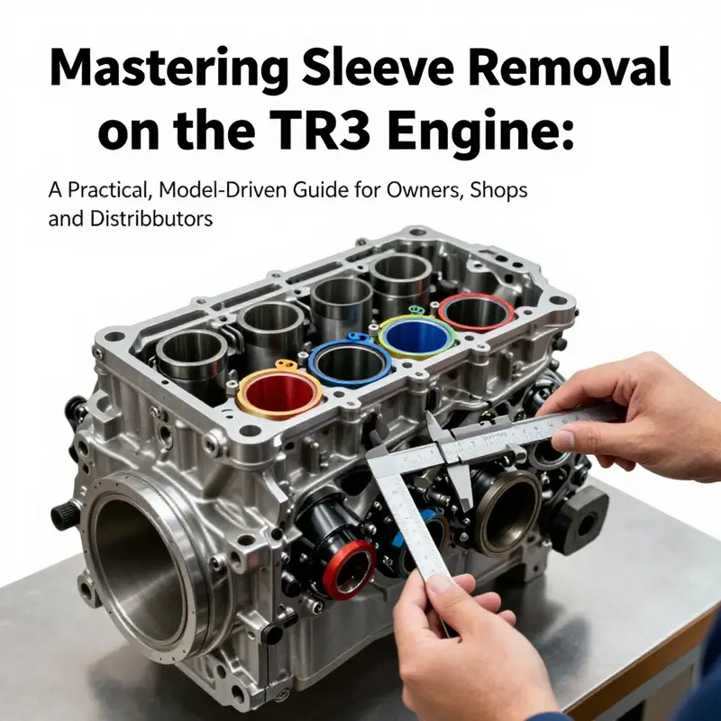
The procedural core begins with a complete disassembly. The first step is to remove the cylinder head, followed by the pistons and connecting rods, and finally the crankshaft. This sequence is deliberate: you need unobstructed access to the sleeve edge and the outer surface of the sleeve itself. With the components out of the way, the sleeve puller becomes the central tool in the operation. A sleeve puller is designed to grip the sleeve’s outer surface without marring the finish, allowing for even, controlled extraction. The technique is to place the puller so its jaws bite into the sleeve where there is solid metal to grip and then apply pressure evenly. The slow, deliberate tightening of the puller screw is crucial. It minimizes the risk of distorting the bore or introducing a runout that could compromise a fresh fitting. The TR3 sleeve, given its press-fit nature, responds to gradual force rather than quick, forceful action. If resistance remains high, a measured application of heat can aid the process, but the heat must be controlled and localized to avoid warping the block. A heat gun is a practical choice here, used to expand the block’s metal slightly around the sleeve edge to help with release. The safest practice is to avoid striking with hammers or chisels, which can crack the block or nick the bore surface. The objective is to draw the sleeve free with minute attention to surface integrity and alignment.
An important anatomical detail guides a portion of the workflow: during reassembly, the connecting rod bearing cap must face the camshaft side of the engine for proper alignment and clearance. This orientation ensures that the piston and rod assembly will have adequate space, and that no unintended interference surfaces arise between the rod cap and any nearby features in the block. In practice, this means that when you reassemble the components after sleeve work, you orient the cap correctly before torquing the bolt pattern. It is one of those subtle steps that establishes a reliable baseline for the entire cylinder package. Attention to such orientation underscores a broader principle: the engine is a system with clear spatial relationships. A misstep here can lead to contact with the camshaft or with the cylinder wall, potentially causing a costly rework.
Once the sleeve begins to break free from the block, patience remains the guiding virtue. The extraction process should be smooth, with particular care not to tilt or cock the sleeve. A straight, coaxial withdrawal preserves the bore’s integrity and leaves a clean seating surface for the new sleeve. After removal, the bore should be inspected for scoring, taper, or ovality. If any damage is detected, the block may require reconditioning or a bore finish to spec before fitting a replacement sleeve. The measurement phase is not merely a formality; it provides the crucial data that informs whether you will reuse a sleeve (in rare cases where the sleeve is in good condition) or whether you will source a fresh sleeve that matches the engine code and bore dimension precisely. In any case, the outer diameter of the sleeve and the inner diameter of the bore must be within tolerance for a proper press or slip fit. The cleanliness of the surface cannot be overstated. Debris at the bore edge can spoil the seal, hinder seating, or cause a misalignment that will reveal itself as a leak or a loss of compression after reassembly.
The compatibility question follows naturally from the mechanical realities just described. The engine code and the sleeve dimensions must be cross-checked against the intended replacement. Mixing sleeves of the wrong material, thickness, or shoulder configuration can produce a cascade of problems, from misalignment to rapid wear. The TR3 engine design is sensitive to these parameters; even a small deviation in seating depth or bore diameter can shift the piston’s clearance, alter heat transfer properties, or disturb coolant flow around the bore. In a broader sense, this is why a service manual specific to the exact model year is not a luxury but a safeguard. The absence of such documentation elevates the risk of a failure that could be expensive to diagnose later. The general guidance is to source sleeves that match the exact engine code, and to verify both the external dimensions and the shoulder geometry that supports the sleeve and seals the interface with the block. If the sleeve is the wrong type, you may encounter issues with concentricity, gaps at the interface, or leakage paths that undermine the cooling or lubrication system.
The reconditioning phase after sleeve removal is as crucial as the removal itself. If the sleeve is to be reused, verify its outer diameter, surface finish, and ring seating features. If a new sleeve is installed, follow the manufacturer guidance on interference fit or expansion fit and apply lubrication to the sleeve’s outer surface to prevent galling during seating. The seating operation must be controlled and consistent; uneven seating can introduce a local hotspot, cause distortion, or lead to coating damage if a sleeve has a protective coating. The seating depth is a critical parameter; if it is too shallow, you risk a bore that does not properly seal with the head gasket or a piston that sits awkwardly within the bore. If too deep, you may alter compression distance, piston geometry, and ultimately the engine’s dynamic balance. Post seating, the block should be cleaned of metal shavings, debris, and residues generated during the process. A careful flush of coolant channels is mandatory to prevent any particulate matter from migrating into the water jacket, especially if a wet sleeve is involved. The restoration of the deck surface is not just cosmetic; it ensures a proper head gasket seal and predictable head bolt clamping behavior.
The broader quality control frame for sleeve removal emphasizes documentation. Every measurement taken before, during, and after the work should be captured in a maintenance log. Photos of the bore edge, the sleeve seat, and the alignment features are invaluable when reassembling or diagnosing a future issue. A practical approach is to perform leak-down and compression tests after reassembly to verify cylinder integrity. If the engine fails to hold pressure or leaks through the coolant system at the sleeve interface, the root cause will likely trace back to an improper seating or an incompatible sleeve. The process is not merely mechanical; it is a sequence of checks that verify the engine’s geometry and seals have returned to a state of reliability. In the end, sleeve removal is a respect-for-detail exercise. It asks you to understand the particular design of the TR3 block, to apply a method that preserves bore integrity, and to reassemble with attention to the precise orientation of components and the correct seating depth for the new or renewed sleeve.
For readers seeking a practical, hands-on walkthrough that complements this chapter, a focused resource on the exact removal technique is available. See How to Remove Engine Sleeves for a practical guide that aligns with the general principles outlined here and offers step-by-step demonstrations aligned with typical sleeve puller usage and heat-assisted release. This reference helps translate the conceptual framework into actionable steps you can apply to the Triumph TR3 context while keeping in mind model specificity and the need for the appropriate tooling. How to Remove Engine Sleeves
As you close the sleeve removal phase and move toward reassembly, bear in mind that compatibility remains the thread tying every decision together. The exact sleeve type dictated by the engine code, the measurement tolerances for bore and seating depth, and the appropriate lubricant or anti-seize selection are all pieces that must align with official guidance. The absence of a model-specific manual does not absolve you from these responsibilities; it intensifies them. When in doubt, the safest route is to reference the factory service documentation that corresponds to your engine variant, contact a specialist who can confirm the sleeve type, and source a sleeve from a supplier who can provide a true match in material, coating, and dimension. The traceability of components matters not just for performance but for future serviceability. The TR3’s legacy relies on precise fitting and careful workmanship. The sleeve, once properly removed and replaced, becomes a durable interface between the combustion process and the engine’s cooling and lubrication systems. The outcome hinges on your ability to manage heat, measure accurately, and maintain the structural integrity of the block.
External resources can provide valuable corroboration and deeper theorems on sleeve behavior across engines. For readers who want a broader, external reference on classic engine sleeves and restoration practices, consult a dedicated factory service manual or reputable archival resources that cover the Triumph TR3 family. External reference: Triumph TR3/TR3A Factory Service Manual provides the definitive guidance on sleeve type, seating depth, and removal sequence. https://www.triumphspares.com/manuals/tr3a-factory-manual/
Sleeve Extraction in the TR3: Precision, Patience, and Reclaiming a Cylinder Block

Removing cylinder sleeves from a TR3 engine is a possession of patience as much as it is a test of technique. What begins as a routine teardown can quickly become a high-stakes precision task when the goal is to preserve bore geometry, coolant passages, and the structural integrity of the block. The material here is compiled not as a model-specific manual, but as a cohesive narrative that threads general sleeve-removal principles with the particular rhythms of a classic TR3 engine. In absence of an official, model-specific procedure, the core guidance remains anchored in controlled disassembly, correct tooling, and rigorous verification. The route from a complete engine to a sleeve-free block, or to a refreshed sleeve-set, demands a deliberate sequence, a well-chosen set of tools, and a mindset that prioritizes cleanup, measurement discipline, and meticulous reassembly. The TR3 sleeve removal we describe below is framed to be applicable in a workshop that respects both traditional craftsmanship and modern metrology, while clearly signaling when model-specific specifications must take precedence.
The journey begins with a recognition that sleeves, whether wet or dry, are more than skinny tubes in a bored block. They are interfaces—the boundary between the piston’s world and the engine’s cooling and lubrication channels. Disturb that boundary without care, and you invite a cascade of problems: distortion at the deck, misalignment of the bore, or coolant and oil passages contaminated by debris. The research base for this discussion points to two essential truths: first, the TR3 engine family has variations, and second, the safe, reliable removal of sleeves hinges on identifying the exact sleeve type, retention method, and seating depth before any tool is put to work. With that preface, the disassembly must proceed in a disciplined, stepwise fashion that keeps the block’s planes true and the bore surfaces pristine.
The first practical decision is whether the engine is still in the vehicle or already out on the bench. Removing the engine from the chassis is the conventional starting point for serious sleeve work because it affords better access to all sides of the block and the sleeve edges without fighting the street or the engine’s own original mountings. Once the engine is free, the cylinder head becomes the initial target for disassembly. The cylinder head does not merely sit atop a block; it anchors the fate of the bore’s surface when the head gasket is compromised or the deck surface has run through its service life. The typical sequence is to remove the head bolts in a crisscross pattern to minimize warp, lift the head, and inspect the gasket surface for any galling, pitting, or uneven wear. This step may reveal depth shifts, water jacket contamination, or gasket remnants that could influence later sleeve seating. The emphasis here is not to rush, but to observe and document the head’s condition as it relates to the impending bore work.
Moving deeper, the piston and connecting rod assemblies represent a sensitive transition from top-end disassembly to the heart of the engine’s motion. In a careful teardown, main bearing caps and rod caps are removed in sequence, or at least in a way that preserves their original locations. The pistons and rods are withdrawn through the top of the cylinder bores with the block’s alignment in mind, ensuring the piston rings do not dig into the fresh bore edge or the sleeve edge later. This step is more than mechanical removal; it is a check against misalignment that could produce scuffing later in reassembly. The goal is to keep each component’s orientation and position recorded, so reassembly can be faithful to the engine’s original geometry.
With the pistons and rods safely removed, access to the sleeves becomes feasible. The sleeves in a classic TR3 are pressed into the block or otherwise retained by bottoming features, depending on the exact design employed in a given production run. This is where the distinction between wet sleeves and dry sleeves becomes crucial. Wet sleeves occupy the coolant passages and are cooled by the engine’s water jacket; their removal must be conducted with special care to avoid contaminating or obstructing the cooling channels. The extraction is typically performed with a sleeve puller that engages the sleeve’s outer diameter and applies even force while supporting the bore from behind. The risk with wet sleeves is not merely breaking the sleeve; it is cracking or bending the block’s edge around the bore if misalignment occurs during extraction. For dry sleeves, where the sleeve is held by an interference or mechanical retention rather than immersion in the water jacket, the extraction approach often involves controlled heating, cooling, or a combination along with a precise driving force to release the interference fit. A two-stage approach—slightly expanding or shrinking the sleeve, then sliding it out—can prevent the block from distortion and avoid galling at the sleeve-block interface.
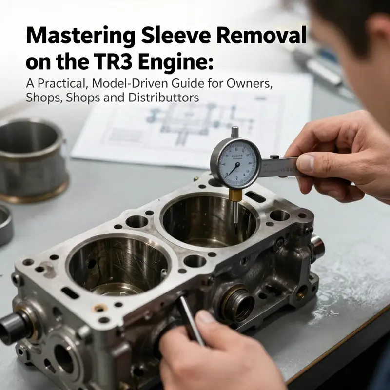
A consistent theme throughout this phase is the necessity of a well-prepared tooling set. A sleeve puller with adjustable jaws designed for the block’s geometry is indispensable. The tool should grip the sleeve’s outer surface without biting into the bore edges or mangling the block’s shoulder. A soft-faced hammer and a drift are useful for initial loosening, but they must be used with restraint to avoid imparting localized shocks that could warp the bore. An arbor press or a hydraulic ram provides the controlled, progressive force needed for extraction, especially when the sleeve is stubbornly seated. The use of heat for dry-sleeve scenarios must be carefully controlled—uniform heating to a safe temperature helps to relieve interference without causing thermal distortion in the block. The sequence also calls for precision measurement tools: bore gauges, micrometers, dial indicators, and straightness checks to verify that the block’s bore remains true. Each sleeve’s journey—whether out, in, or replaced—needs to be documented with measurements that future technicians can rely on when setting tolerances for a new sleeve or reconditioning the bore.
As the sleeve edge is finally exposed, the removal technique must pivot from extraction to protection. The edge of the bore, the corner radii, and the bottom shoulders are all critical in the subsequent sleeve seating process. Debris left in the water jackets or on the bore surface can cause an ill-seating or micro-scorning that undermines compression and cooling. The removal operation should conclude with a careful wipe and inspection, applying a thin film of lubricant to the sleeve edge if a new sleeve is to be inserted and ensuring that no oil films or cleaning solvents linger where they could contaminate a fresh seal. It is here that the practitioner should examine the block for any signs of subtle distortion near the bore—such distortion may not be visible at first glance but can emerge after the sleeve is removed and the block is re-measured.
Documentation becomes not only prudent but essential at this juncture. The sleeve’s location, its outer diameter, and how it was retained must be recorded. If the sleeves are to be reused, their exterior must be measured for diameter and compared to the block’s bore to assess concentricity and interference fit. If a reconditioning plan is chosen, the block’s bore might require honing or reboring to accept a new sleeve with the proper wall thickness and surface finish. In either case, the goal is a clean, uniform seating surface with no burrs or edge defects that could impair the sleeve’s seat. The integrity of the block’s deck surface and the alignment of the cylinder bores are prerequisites for a successful reassembly.
For the TR3, a practical reminder is that the exact procedure—whether the sleeves are wet or dry, the depth to which they seat, and the tolerances to be observed—depends on the specific variant and year. The absence of a singular, official TR3 sleeve-removal manual means the technician must lean on general, proven practices while staying alert to model-specific notes when they become available. The general workflow described here aligns with the common engineering approach: approach the task with a plan, expose the sleeves with clean access, remove them without gouging the block, and leave the block in a condition that permits reliable re-sleeving or re-boration. It is a workflow that respects the delicate balance between force and finesse, between the need to free a stubborn sleeve and the responsibility to preserve the engine block’s long-term integrity.
With the sleeves removed, the block can enter a phase of reconditioning or preparation for a new sleeve set. Cleaning the coolant passages, removing deposits, and inspecting all water jackets becomes the routine. Debris must be flushed out; freeze plugs and passages should be checked and replaced if necessary. If re-sleeving, the outer diameter of the new sleeves, the seating depth, and the interference-fit or expansion requirements must be observed exactly. A light coat of lubrication on the sleeve’s outer surface reduces galling during seating, and the seating force—whether hydraulic or mechanical—must be controlled to prevent distortion. The reassembly sequence then proceeds with the reinstallation of sleeves, bore alignment checks, and a renewed cycle of torqueing, gasket seating, and ring seating.
Quality control remains a thread that runs through the entire operation. Before final assembly, a thorough inspection of every bore and sleeve surface ensures there are no micro-scratches that could become fault lines under heat and pressure. After assembly, leak tests and compression checks reveal the health of the cylinder set. A borescope inspection can confirm concentricity and bore finish at the sleeve interface. If measurements deviate from the acceptable range, corrective actions must be taken, which could include re-honing, re-sleeving, or even engine-block refurbishment. This is not merely a check of whether the engine turns over; it is a validation that the bore geometry, sleeve seating, and cooling passages will work together under load and heat.
The economic and logistical realities of a sleeve-removal project should not be underestimated. The time, specialized tooling, and potential need for re-sleeving or re-boring contribute to a substantial cost. In many cases, the block’s reusability hinges on whether the sleeves can be removed cleanly and whether the block can tolerate the reconditioning required for a reliable seal and bore finish. Supplying sleeves, maintaining the correct tolerances, and aligning the reassembly steps to the engine’s original geometry all have direct implications for reliability and longevity. The broader context reminds us that skill, patience, and a systematic approach are the most valuable tools in this task.
One practical note for readers seeking a concrete, field-tested guide is to consult a focused, model-relevant resource. A detailed, procedure-oriented reference can provide the exact fixture alignments, torque values, and seating depths that a hobbyist manual cannot supply. For readers who want a rigorous, model-specific anchor, the following online resource can be a useful complement to this discussion: how-to-remove-engine-sleeves. This internal link provides a more granular, tool-specific sequence that aligns with the general approach outlined here. how-to-remove-engine-sleeves.
As a final note, the TR3 sleeve-removal topic is intertwined with the broader engine-sleeving landscape. The mechanical and thermal demands of sleeves, and the consequences of improper removal, reinforce that this is a task best undertaken with a clear plan, a documented approach, and the humility to consult model-specific service information when it becomes available. The procedure described above is built on cross-cutting engineering practices applied to many engines, tempered by the realities of a classic British inline-four with its own quirks and historical nuances. The objective remains consistent: remove sleeves without compromising the block, ensure bore geometry survives intact, and provide a pathway for reliable reconditioning or re-sleeving that preserves the engine’s performance and longevity.
External reference: For authoritative, model-specific specifications and procedures, consult the official factory service manual at https://www.triumphspares.com/manuals/triumph-tr2-tr3-tr3a-factory-service-manual
null
null
Final thoughts
TR3 sleeve removal is a high-precision workflow that begins with identifying sleeve type and compatibility, continues through a disciplined disassembly using the correct tools, and ends with rigorous inspection and reconditioning decisions. Adhering to model-specific specifications, maintaining cleanliness, and documenting measurements are the building blocks of reliable reassembly. When in doubt, consult the official TR3 service manual or seek guidance from a qualified shop to protect block integrity and coolant/lubrication pathways for long-term engine health.