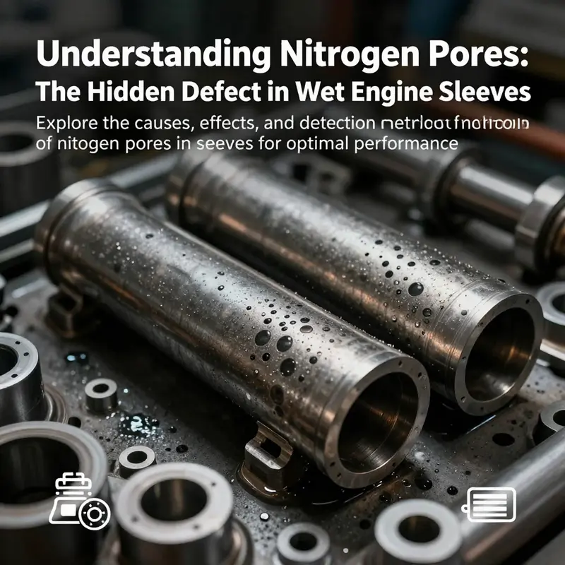
Holes in wet engine sleeves, often seen as mere manufacturing quirks, signify crucial underlying issues that can affect engine integrity and performance. Often referred to as ‘nitrogen pores,’ these defects arise during the casting process, impacting motorcycle and automobile engines alike. As a motorcycle owner, car enthusiast, or a professional in the automotive industry, understanding these pores will help you address potential failures and persistently leaking engines. Throughout this article, we delve into the implications of nitrogen pores in engine sleeves, examining their origins, the impact of casting quality, the manufacturing processes involved, and the advanced detection methods that can recognize these ominous flaws before they lead to catastrophic failures.
When Sleeves Leak: Why Cavitation, Not Nitrogen Pores, Creates Holes in Wet Engine Liners
Understanding why holes appear in wet engine sleeves requires separating two different failure modes that are often confused. On one hand, metallurgists describe porosity and gas-related voids in cast components. On the other hand, engine technicians face a slow, destructive process that chews holes through liners that sit directly in coolant. These are not the same problem, and conflating them leads technicians and owners to the wrong diagnosis and wrong fixes.
To begin, it helps to define the parts. A wet sleeve, or wet cylinder liner, is a removable metal tube that forms the combustion wall. Its outer surface contacts coolant. The sleeve is exposed to alternating pressure and temperature cycles at the combustion side. If you need a quick primer on liners, see this short overview of what engine sleeves are and how they function: what are engine sleeves.
There is a documented casting defect called porosity in certain engine blocks. In some large iron castings, microscopic voids appear when dissolved gases leave the melt during solidification. These voids sometimes concentrate at specific features. Engineers have found them near oil holes, cam bores, and valve guide areas in blocks. When porosity occurs at a sealing surface it can let oil or coolant escape. That type of defect is real and important in block manufacture. It is not, however, the typical cause of holes in wet sleeves.
The phenomenon that actually produces holes and heavy pitting in wet sleeves is cavitation erosion. Cavitation begins when the pressure of the coolant drops locally below the vapor pressure. Tiny vapor bubbles form. When those bubbles collapse they unleash micro‑shock waves. Over many cycles the metal surface is hammered. Small pits form. Those pits grow, link up, and eventually become through‑wall holes. Cavitation is a mechanical and hydraulic process, not a gas‑solubility issue in a casting.
Cavitation prefers certain conditions. High coolant velocity, abrupt changes in flow direction, sharp edges, and localized heating all favor bubble formation. The skirted geometry of a wet sleeve, with tight gaps and often turbulent flow at the top edge, produces ideal spots for cavitation. Cylinder pressure pulses and intake suction at the water pump can lower local coolant pressure, too. Where the flow is most energetic you see the first signs of pitting.
Coolant chemistry plays a surprisingly large role. Modern coolants are not just heat‑transfer fluids. They contain inhibitors designed to raise the boiling point, prevent corrosion, and cushion tiny vapor events. A mixture that is too watery loses those properties. Ethylene glycol, for example, raises boiling point and dampens bubble formation. It also carries additives that reduce surface tension and inhibit cavitation‑related corrosion. Running plain water or a poorly formulated mix increases cavitation risk. The wrong antifreeze concentration allows vapor pockets to persist and collapse more violently.
Air in the system also matters. Entrained air makes bubble nuclei more plentiful. That increases both the size and frequency of collapse events. A system full of microbubbles will amplify cavitation damage. That is why proper bleeding of the cooling system during service is essential.
Material and surface condition determine how quickly cavitation eats through a sleeve. Soft cast iron erodes faster than hardened steel. A rough surface gives more initiation sites than a smooth finish. Manufacturing tolerances, metallurgical heat treatment, and surface treatments such as hardening or protective coatings influence resistance. Many engine builders use liners with specialized finishes or coatings precisely to slow cavitation erosion in the most exposed zones.
Design choices can either invite or reduce cavitation. Sleeve crown shape, water jacket geometry, and the proximity of coolant flow channels to the combustion face are all influential. If a water jacket produces a high‑speed jet near the top of the sleeve, cavitation will be far worse. Heavy turbulence from sharp corners or unsupported core sections in original casting tooling can exacerbate the problem. Redesigning water jackets to smooth flow and eliminate eddies is a common engineering countermeasure.
It is worth clarifying where nitrogen pores and similar casting voids fit into the picture. When found, nitrogen pores are typically microscopic cavities trapped in the matrix of a casting. They appear during solidification if dissolved gases cannot escape. In blocks, they may create leakage at specific bores or oil holes when a defect intersects a passage. Detecting these flaws requires non‑destructive tools such as X‑ray imaging, tomography, or dye penetrant inspection after sectioning. When porosity is the root cause of leakage, the fix is a manufacturing control change, not coolant chemistry or antifreeze tweaks.
Contrast that with cavitation. Cavitation creates pitting on the working surface after service, often far from any casting joint or core insert. Its signature is mechanical erosion with rounded pits and scalloped edges. The damage pattern is progressive and correlates with operating time and coolant condition. In many service records, cylinders with cavitation holes show heavy pitting near the top ring land or just below the deck. That distribution reflects fluid dynamics more than casting faults.
Diagnosing the real problem demands careful inspection. If you suspect porosity, sectioning and metallographic analysis reveal trapped voids. Non‑destructive imaging finds internal defects in cast blocks. If you suspect cavitation, a visual exam of the liner surface tells the story. Pitted surfaces with rippled edges and collapsing pits that follow coolant flow patterns indicate cavitation. Checking coolant mixture, pump condition, thermostat behavior, and air removal completes the assessment.
Repair strategies differ accordingly. If casting porosity creates leakage, the block often needs replacement or skilled repair at the manufacturer level. Porosity at critical passages is not reliably fixed with a local patch. When cavitation has eaten a hole in a liner, options include sleeving repairs, replacing the liner, or using a liner with a tougher surface treatment. Exhaustively addressing the hydraulic cause is essential. Replacing the sleeve while leaving the same coolant condition will invite recurrence.
Prevention focuses on both design and maintenance. Good design smooths coolant flow and reduces pressure dips. Adequate liner material and surface protection reduce erosion rates. Maintenance keeps the coolant chemistry stable and the system free of air. Regular fluid changes preserve inhibitor levels. Replacing weak or clogged thermostats and maintaining pump clearance reduces excessive suction or vapor zones.
A few practical maintenance tips reduce cavitation risk. Use the correct coolant formulation and maintain the recommended concentration. Avoid using plain water when antifreeze and inhibitors are specified. Follow service intervals for coolant change. Bleed air thoroughly after any coolant service. Inspect the cooling fan, shrouding, and pump operation for irregular flow. Finally, if you see early pitting, stop operation and diagnose. Cavitation damage accelerates quickly once patterning starts.
There are engineering countermeasures that go beyond routine service. Coatings such as hard finishes and certain thermal sprays increase cavitation resistance. Sleeve designs with thicker crowns in vulnerable areas reduce material loss. Water jacket redesign can remove turbulent jets. In manufacturing, controlling casting quality removes the separate risk of porosity in the block itself. Modern production uses computed tomography and pressure testing to catch porosity before assembly. These steps prevent confusion where two different failure modes might be blamed for the same symptom.
It is tempting to reach for a single cause when holes appear in a cooling‑exposed liner. Too often the scapegoat becomes a gas void in the metal. That explanation fits when discussing block castings, where nitrogen and other dissolved gases create defects. But wet sleeves fail for a hydraulic reason in most in‑service examples. Cavitation eats through metal that directly faces coolant pressure cycles and turbulent flow. Confusing the two delays the right remedy and wastes time and resources.
In short, when wet engine sleeves develop holes, the working assumption should be cavitation erosion. Only after ruling out surface cavitation and the cooling system’s role should casting porosity be considered. Proper inspection, correct coolant chemistry, diligent bleeding of air, and design checks protect liners. When porosity is present elsewhere in the block, manufacture and inspection protocols must be tightened. Each pathology has different diagnostics and different fixes.
For a deeper technical review of cavitation effects on cylinder liners, the following resource provides a focused analysis of mechanisms and mitigation strategies: https://www.engineer.com/cooling-systems/cavitation-erosion-in-engine-cylinder-liners
When Casting and Cavitation Collide: How Production Quality Influences Holes in Wet Engine Sleeves
Understanding why holes appear in wet engine sleeves requires looking at two linked realities: the mechanical forces that produce cavitation and the material weaknesses that make cavitation’s damage stick. Many workshops and service manuals point to visible pits and needle-like holes and assume a single cause. In truth, the holes you see are most often the end result of an active erosion process — cavitation — but the pace, pattern, and severity of that erosion are shaped by how the sleeve and block were made.
Cavitation is a fluid-mechanics phenomenon. Rapid pressure fluctuations in the coolant cause tiny vapor bubbles to form and collapse repeatedly near a metal surface. Each collapse generates a micro-jet and a shockwave. Over thousands to millions of cycles, these impacts remove metal at a microscopic scale. On a wet sleeve, cavitation produces characteristic pits, clusters of tiny depressions, and, eventually, larger craters. This is the direct, mechanical origin of the holes commonly observed around coolant passages and along the outer diameter of liners.
Casting quality does not create cavitation. But it influences how quickly cavitation creates visible damage, and whether that damage opens into persistent holes or remains superficial. Castings are not perfectly homogeneous. During production, variables such as melt chemistry, gas content, cooling rate, and core integration determine the metal’s microstructure and the presence of defects. Where the metal is weaker or contains voids, the metal yields faster under the same cavitation loading. Thus, poor casting quality acts as an accelerant for a problem born of dynamic fluids.
One common casting defect is porosity caused by trapped gases. When molten iron or an alloy cools, dissolved gases — nitrogen, hydrogen, or others — may form bubbles that become locked into the solid metal. These nitrogen pores or gas pockets concentrate stress under mechanical impact. A collapsing vapor bubble striking a perfectly dense, well-bonded iron matrix will remove metal slowly. The same impact against a matrix with internal porosity can break through thin ligaments of metal, exposing and enlarging the pore and producing a visible hole far sooner. Electron microscopy and sectioning of failed blocks routinely find nitrogen pores clustered around oil holes, cam bores, and lifter locations. Those findings explain why some parts fail more readily than others under similar service conditions.
Beyond gas porosity, inclusions and poor fusion in the casting process also matter. Nonmetallic inclusions — slag, sand, or resin remnants from cores — act as initiation points for localized erosion. Poor fusion between core supports, such as core-bridges, or inadequate contact between chill iron inserts and the surrounding cast material creates weak interfaces. Under cavitation loading, these interfaces can separate or spall, revealing voids or stepping the surface profile into pits that trap and concentrate coolant flow. The result is a patchy, irregular pattern of holes rather than an evenly worn surface.
Microstructure matters too. The hardness and toughness of the liner and surrounding cast iron define how it responds to repeated micro-impacts. A fine, homogeneous graphite distribution and controlled pearlite-ferrite balance produce a surface that resists fatigue from repeated impacts. Conversely, a coarse or brittle microstructure chips away faster. Alloy additions and inoculants during melting alter graphite morphology. Cooling rates affect chill depth and the formation of hard spots or weak zones. The cumulative effect is a variation in local resistance to cavitation across the sleeve surface.
Manufacturers can reduce susceptibility through casting controls. Vacuum degassing lowers dissolved gas content. Proper gating and riser design reduces turbulence in the mold and limits air entrapment. Using higher-quality core materials and ensuring proper core support reduces poor-fusion zones. Controlling cooling rates and using post-cast heat treatments refine the microstructure. Each of these steps raises the metal’s baseline resistance to cavitation and to the formation of secondary defects that turn micro-erosion into full holes.
Detection and quality assurance also change outcomes. Traditional visual inspection misses subsurface porosity. Advances in inspection such as X-ray tomography, computed radiography, and even simple pressure testing can reveal hidden cavities and poor core integration. Banks of modern machining centers now include in-line nondestructive testing to reject suspect blocks before assembly. When porosity is discovered early, a casting can be reworked or scrapped rather than becoming a leaky engine in the field.
Yet casting improvements and inspection do not solve the fluid-mechanics root cause. Engine designers must pair improved materials with changes in coolant dynamics to control cavitation. Cavitation intensity depends on local pressure swings, flow velocity, and proximity of structural resonances. Sleeves positioned where coolant flow is turbulent or trapped are more at risk. Sharp corners, abrupt changes in cross-section, and stagnant pockets invite bubble formation and violent collapse. Design choices such as smoothing coolant paths, avoiding sharp edges, and maintaining continuous flow across vulnerable surfaces reduce cavitation initiation.
Operational conditions also influence how casting defects translate into holes. Low coolant levels or improper coolant formulation increase the volume of vapor that can form. Air pockets in the coolant create local low-pressure zones and amplify pressure pulses. High engine speeds change vibration frequencies and may align with natural resonant modes in the cylinder head or block. Field maintenance practices — flushing the cooling system, maintaining the correct coolant concentration, and ensuring the system is free of entrained air — therefore reduce the likelihood that a casting defect will evolve into a troublesome hole.
When a block already shows cavitation damage, repair choices are guided by the cause and extent of damage. For small, shallow pits, material-nondestructive-restoration techniques like thermal spraying, plasma coatings, or even micro-welding can re-establish a hard, continuous surface. These methods build up metal in the damaged zones and are effective where the underlying substrate is sound. If porosity is extensive or near critical sealing surfaces, sleeve replacement or installing a dry sleeve may be the only reliable fix. Repair shops must assess whether the substrate will support a coating or if metallurgical instability will cause the new layer to fail prematurely.
Modern liners use material science to stay ahead of cavitation. Hardened castings, coated liners, and alloyed sleeves increase surface hardness without sacrificing toughness. Thermal-spray coatings, chrome plating alternatives, and nitriding deliver harder surfaces that deflect the micro-jets produced by collapsing bubbles. These solutions change the interaction between collapsing vapor bubbles and the metal. A harder, denser coating absorbs less energy per impact and resists metal loss longer. But coatings only work when they bond to sound material. If the casting beneath contains large pores or delaminating interfaces, coatings will crack and peel under repeated impact.
The manufacturing process has evolved to address both casting defects and the cavitation that exploits them. The combination of better mold materials, controlled melting, improved core technology, and in-line nondestructive testing is reducing the incidence of cast-in porosity. Meanwhile, engineers optimize coolant passages and introduce physical changes such as ribs or damping features to lower vibration amplitudes and alter resonant conditions. This two-pronged approach — make the metal better and make the fluid environment kinder — is the most practical path to fewer holes.
Finally, understanding failure requires good diagnosis. When a sleeve shows holes, the pattern of damage tells a story. Clusters of shallow, fine pits near high-flow regions point to classic cavitation. Isolated holes surrounded by a sudden transition often indicate a casting defect opened by erosion. Microscopy can reveal oxygen-rich or nitrogen-rich interiors, indicating trapped gases. Sectioning the casting can show poor fusion lines and core-bridge detachments. Effective diagnosis informs whether the fix is operational, metallurgical, or both.
In short, holes in wet engine sleeves are the visible outcome of cavitation interacting with material weaknesses. Casting quality does not create the cavitation, but it determines how vulnerable a sleeve will be to the steady assault of collapsing vapor bubbles. High-quality castings with low porosity, proper fusion, and refined microstructure resist cavitation better. Complementing those standards with coolant-flow design, proper maintenance, and targeted surface treatments provides a durable defense. For a clear technical treatment of how cavitation forces act on wet liners and the material considerations to counter them, refer to the Society of Automotive Engineers technical paper on cavitation erosion in wet liners: https://www.sae.org/publications/technical-papers/content/2015-01-0374/.
For a basic refresh on liner types and how wet sleeves sit within the engine’s cooling and thermal-management system, see this primer on what are engine sleeves: https://itw-autosleeve.com/blog/what-are-engine-sleeves/.
Why Wet Sleeves Have Holes: Casting Realities, Cooling Needs, and the Porosity Problem
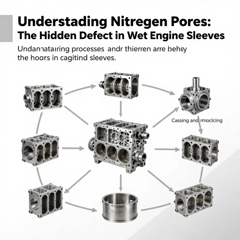
Wet cylinder sleeves look simple at first glance: a metal tube slipped into an engine block. But that tube often has small holes and features that are essential to how the engine manages heat. Understanding why those holes exist requires following the sleeve from molten metal through casting, machining, and final assembly. It also requires confronting a parallel reality: not all holes are intentional. Some are defects that weaken the block and cause leaks.
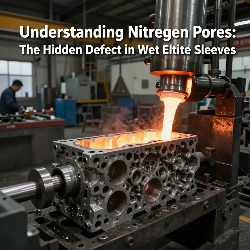
The manufacturing journey of a wet sleeve begins with material selection and casting. Manufacturers commonly use high-grade cast iron or specific steel alloys for sleeves. These materials resist wear from pistons and rings and handle repeated thermal cycling. Molten metal is poured into molds shaped to produce the sleeve body. At this stage the goal is twofold: form the correct gross geometry, and control the metal’s internal structure so the sleeve will transfer heat and seal reliably once installed.
Casting is deceptively complex. Molten metal cools and solidifies from the outside inward. As this happens, gases dissolved in the liquid can come out of solution and become trapped. Nitrogen and other dissolved gases form tiny voids, or pores, in the solid metal. These voids are often microscopic, but when they collect near crucial features they become performance risks. Engineers sometimes call them nitrogen pores or porosity. When porosity occurs near oil holes, lifter bores, or coolant passages, it can open a path for oil or coolant to leak past sealing surfaces.
A separate, intentional set of holes is placed in wet sleeves to support cooling. Unlike dry sleeves, which sit tight inside the block and rely on the block to carry away heat, wet sleeves are directly exposed to coolant. Manufacturers drill or cast small openings at predetermined positions so engine coolant can wash the outside of the sleeve evenly. Those deliberate holes let coolant flow through the annular space around the sleeve and allow heat from the combustion chamber to transfer quickly into the cooling system. Properly designed, those ports reduce hot spots and stabilize cylinder wall temperature. That stability helps the engine resist warping, reduces detonation risk, and extends component life.
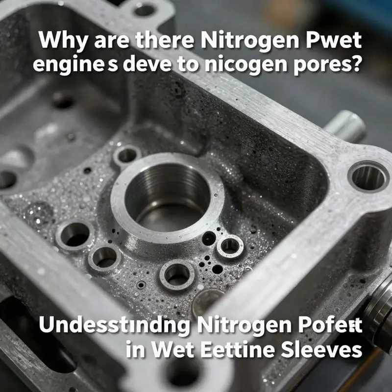
Problems begin when unintended porosity mimics or undermines these designed passages. The same micro-voids that are innocuous in a thick, low-stress area become critical when they appear along an oil passage or near a sealing face. During solidification, poor fusion between core supports and metal inserts, or between different casting inserts, creates weak zones. In some high-strength gray iron blocks, electron microscopy and sectioning have revealed nitrogen pores in places such as φ6 and φ20 oil holes, lifter bores, and valve guide areas. These localized voids connect the high-pressure coolant or oil channels to unintended pathways. Even after the sleeve receives final machining, the internal pores remain as leak routes.
Controlling porosity begins at the casting stage. Melt chemistry matters. Dissolved nitrogen and hydrogen content in the liquid iron can be reduced through degassing practices. Inoculants and alloying adjustments change the way the metal solidifies, encouraging graphite to form in desirable shapes and reducing shrinkage cavities. Core design also matters. The sand or resin cores that form internal cavities must be engineered to allow gases to escape during pouring and solidification. Poor core support or weak bonding at core-bridge interfaces creates fusion gaps where metal does not flow properly. Those gaps are prime sites for porosity and incomplete fusion.
Thermal management during pour and solidification is another lever. Rapid cooling in some spots and slower cooling in others create thermal gradients. Chill inserts and controlled cooling can direct solidification so that shrinkage porosity forms in deliberate riser zones, which can be machined away. Without those controls, porosity appears where it harms strength. In many modern foundries, chills, feeders, and simulation tools are used to shape the solidification front and keep critical surfaces dense and pore-free.
After casting, sleeves undergo extensive machining. CNC operations bring inner and outer diameters into tight tolerance. Machining also reveals hidden defects. When a drill or boring tool breaks through a sub-surface pore, it can create a through-hole that was not intended. That is why inspection after machining is critical. Visual checks catch obvious flaws, but internal porosity requires non-destructive testing. Radiography, ultrasonic testing, and X-ray tomography are common techniques. They reveal internal voids before the sleeve is assembled into a block. Pressure testing with dyed fluids or air also helps find leaks created by hidden pores.
Sealing a wet sleeve depends on machining accuracy and secondary seals. O-rings, gaskets, and precision end-face finishes keep coolant and oil where they belong. But if porosity opens an unexpected path behind the sleeve, no gasket can fully stop the leak. That is why foundry quality control teams often pair improved casting methods with enhanced inspection protocols. Modern engine plants add X-ray tomography to their workflows and perform pressure tests on critical geometries. Sleeves that pass these tests move forward. Those that do not are scrapped or downgraded.
Design choices also influence the location and size of intentional holes. Engineers position coolant ports to balance flow and mechanical strength. Too many or too-large ports can weaken the sleeve wall. Too few or poorly located ports lead to uneven cooling and hot spots. The trade-off between heat transfer and structural integrity is tight. Computational fluid dynamics and thermal modeling help designers predict how coolant will flow and what temperature gradients will develop. Prototypes reveal where holes should go and how big they must be to avoid cavitation or inadequate flow.
Manufacturing technique affects how well those design choices become reality. Investment casting, centrifugal casting, and sand casting each have advantages and drawbacks. Centrifugal casting tends to produce denser material toward the outside of a sleeve, but if not controlled it can concentrate impurities inward. Sand cores used to create internal features must be robust and well-vented. Resin-bonded cores reduce gas generation but change the surface finish and require different binder burnout profiles. No single method eliminates porosity entirely. Instead, manufacturers select processes that align with material choice, design complexity, and inspection capabilities.
When a block fails in service because of porosity, diagnosis requires careful sectioning and microscopy. Engineers search for telltale signs: spherical voids indicating gas porosity, irregular seams suggesting poor fusion, or shrinkage cavities aligned along the solidification front. The context matters. If pores cluster around core-bridge junctions, the root cause points to core support design. If porosity follows the path of a cooling channel that passed close to an insert, the problem may be contact and bonding between different metal zones. Effective corrective action targets the precise stage where the defect formed.
There are also practical remedies for blocks already in service. In some cases, sleeving or plug-welding can repair a leak. A repair sleeve may be pressed or bonded into the cylinder bore to restore a clean sealing surface and bypass the porous zone. For localized coolant leaks, brazing or metal injection techniques can seal a channel if the area is accessible. These repairs are often labor-intensive and expensive, and they do not address underlying foundry issues. In production, prevention is far cheaper than cure.
Quality control advances have reduced the frequency of porosity-related failures. Better melt handling, degassing, and alloy control lower dissolved gas levels. Core materials and support geometry have matured. Computational casting simulation lets engineers see where porosity will likely form before a tool is cut. Automated X-ray inspection and pressure testing catch parts that would have failed in the field. These steps increase yield and reduce warranty claims.
Still, the interplay of design, metallurgy, and manufacturing means the risk never falls to zero. High-performance and heavy-duty engines push thermal loads to extremes. That increases the consequences of even small defects. Manufacturers must continuously refine sleeve geometry, cooling porting, and casting practice to meet those demands. Designers may alter sleeve wall thickness, relocate coolant ports, or change the positioning of core supports to reduce the probability of harmful porosity. Material scientists may adjust inoculation practices to favor graphite shapes that minimize shrinkage.
Understanding the dual nature of holes in wet sleeves clarifies many engine issues. Some holes are an essential feature, intentionally providing coolant access that reduces hot spots and stabilizes cylinder temperatures. Others are accidental, formed when gases escape during solidification or when metal fails to fuse correctly with cores and inserts. The accidental kind weakens sealing and invites leaks that can be costly and dangerous.
Manufacturers work at three levels to manage both kinds of holes. First, design defines where coolant must reach and how large intentional openings should be. Second, metallurgy and casting technique determine how close to the surface porosity will form. Third, machining and inspection discover any hidden defects and remove or reject flawed parts. When these three levels align, the wet sleeve performs as intended: a durable, well-cooled cylinder wall with reliable seals. When they do not, porosity becomes a persistent source of leaks and failures.
For engineers and technicians, the practical lesson is clear. If a wet-sleeved engine shows a persistent leak around a sleeve, investigation should include both sealing checks and metallurgical inspection. If machining and gaskets are sound, then internal porosity or poor fusion is a likely culprit. Corrective strategies range from targeted repairs to changes in casting and core design. And in procurement, insisting on thorough non-destructive testing and controlled foundry processes pays off in fewer failures and longer engine life.
For readers who want to dive deeper into the role of sleeve porting in cooling, a technical overview of wet sleeve heat control is available that explains how sleeve design shapes coolant flow and temperature distribution. For a deeper look at manufacturing practices for wet cylinder sleeves, see this engineering resource: https://www.engineersedge.com/machining/wet-cylinder-sleeves.htm
For more practical background on the thermal role of wet sleeves in engines, the following internal write-up explains the cooling advantages and trade-offs of wet sleeve designs: wet sleeve thermal management.
Hidden Voids, Hidden Leaks: A Cohesive View of Porosity, Detection, and the Reliability of Wet Engine Sleeves
The question of why holes appear in wet engine sleeves invites a deeper look at the nervous system of an engine component: the way metal solidifies, how gases behave during that solidification, and how even tiny voids can become openings for leaks under pressure. In high-strength gray iron blocks—materials commonly used in robust engine architectures—the so-called nitrogen pores or porosity are not deliberate features but a byproduct of the complex exchange between chemistry, heat, and forming molds. When molten iron begins to transform into a solid, dissolved nitrogen gas can come out of solution and form micro-voids that become trapped within the metal matrix. These voids tend to concentrate in regions that govern critical seals and fluid passages—oil holes, camshaft bores, and valve stem guides—where even a small pore can disrupt the sealing surface or create a channel for fluid escape. The effect is particularly troublesome in wet sleeve configurations, where a sleeve sits within the block and interacts with both oil and coolant networks. A pore near a sealing edge is not merely a cosmetic flaw; it is a potential pathway for coolant to leak into the combustion chamber or for oil to migrate toward coolant channels. In practice, a hole of microscopic scale can, under engine operating pressures, grow into a persistent leak that resists post-assembly sealing and machining corrections. The result is not a one-off defect but a failure mode that challenges both manufacturing discipline and maintenance philosophy.
Academic and industry analyses from the last decade have mapped these porosity patterns with increasing clarity. Porosity in oil passages, lifter bores, and adjacent core-support junctions has been observed in several high-integrity engine blocks, and researchers emphasize that the problem intensifies near interfaces where the core supports fuse with chill inserts. The 2026 synthesis on engine block integrity lays out a connected chain: nitrogen pores arise from trapped gases, and their presence is exacerbated by poor fusion at core-support joints. This creates a synergy where micro-voids not only lower local strength but also create leakage paths. The broader implication is that manufacturing quality control cannot rely solely on surface finishing and dimensional tolerances; it must aggressively interrogate the internal integrity of critical openings. In practical terms, such porosity explains why even perfectly machined seals can fail if the underlying substrate carries hidden voids adjacent to the oil and coolant circuits. As a result, modern production lines have integrated more sophisticated inspection regimes that look beyond surface quality to internal consistency. X-ray based tomography, high-resolution radiography, and pressure-based testing have become standard tools for validating a sleeve-bearing region’s integrity before the engine is ever assembled.
The mechanistic narrative behind these nitrogen pores is anchored in thermodynamics and metallurgy. When the melt cools, nitrogen dissolved in the molten metal can precipitate out, forming small voids that remain locked inside the solidifying material. The cooling rate, alloy composition, and the presence of core materials influence how evenly gas is released and vented during solidification. Fast cooling can trap more gas locally, while slower cooling may allow some voids to migrate and coalesce in weaker regions. In core-and-chill configurations, the interface between the core support and the chill iron insert can become a locus of disrupted fusion, creating stagnant zones where gas can accumulate and pores can grow in size or number. These micro-voids are not visible to the naked eye, yet their closure status under machining is unreliable; the sealing surfaces the industry relies on to keep oil and coolant separate from the combustion chamber may be perched atop a bed of micro-defects that subtly alter surface geometry and enable slow leakage once pressurized. The central point is that porosity is not a mere blemish but a structural hazard that must be interrogated through the entire manufacturing and assembly chain, from material selection and melt treatment to mold design and post-casting inspection.
From a reliability standpoint, the consequences of undetected porosity extend far beyond a single tight leak. If a nitrogen pore intersects an oil passage or a coolant channel, the engine can experience coolant infiltration, leading to hydrolock in the worst cases. Hydrolock occurs when incompressible liquid fills vulnerable volumes under high compression, creating an abrupt stop that can bend or break components and cause catastrophic engine failure. Oil-coolant interactions are equally problematic; coolant dilution of oil degrades viscosity, reduces lubricating film strength, and accelerates wear on crankpins, camshafts, and valve mechanisms. Over time, those wear mechanisms translate into noisy operation, reduced efficiency, and, ultimately, premature failure. In marine or industrial environments, the stakes rise further: leaks may not only reduce performance but also create environmental hazards, regulatory concerns, and costly downtime. The cumulative effect is a stark reminder that the material truth inside a seemingly small hole is a predictor of broader system risk. The challenge, then, is to translate microscopic porosity into actionable manufacturing and inspection strategies that prevent leaks before the engine leaves the shop floor.
To translate this understanding into practice, the detection repertoire has expanded beyond traditional non-destructive testing to include a multi-layered approach that taps into the best of modern technology. Ultrasonic testing (UT) remains a cornerstone for thick-walled components such as wet sleeves. Its strength lies in its ability to scan layered materials and identify hidden flaws, including subsurface voids, with depth resolution. The principle is simple—high-frequency sound waves reflect off discontinuities, and the resulting echoes map the defect landscape. UT is particularly well-suited for identifying internal porosity when performed in resonance modes or with phased-array configurations that can adapt to the geometry of the sleeve and its oil passages. Yet UT is not the only tool; dye penetrant inspection (DPI) offers a complementary view by exposing surface-breaking features that may be connected to subsurface voids. While DPI excels at surface crack detection, its simplicity makes it a cost-effective first line of defense in screening components whose critical regions might reveal a linking fault to the inert voids inside the wall.
Magnetic Particle Inspection (MPI) adds another layer of sensitivity for ferromagnetic materials, highlighting surface and near-surface discontinuities by magnetizing the part and applying ferrous particles that congregate at defect sites. MPI is a rapid, portable option that can be integrated into mid-stream inspections. For truly comprehensive assessment, radiographic testing (RT) uses X-rays or gamma rays to visualize the internal architecture, offering permanent records of the internal condition and enabling observations in geometries where access is constrained. In practice, a robust detection strategy often blends these approaches: UT for internal volumetric assessment, DPI for surface-linked defects, MPI for near-surface anomalies, and RT for complex internal geometry verification. When these techniques are deployed in a targeted sequence—first screening for general integrity, then pinpointing critical regions around oil passages and lifter bores—manufacturers can identify porosity patterns that would otherwise escape routine checks. The broader implication is clear: detection is not a single event but a disciplined workflow that evolves with the component’s criticality and the complexity of its cooling and lubrication networks.
The practical implications of undetected holes extend into the plant and into service life. If a hole exists but goes unseen, a leak that begins as a slow dribble can become a persistent source of energy loss and overheating. Coolant that escapes through a micro-porous path reduces heat transfer efficiency and can push temperatures into ranges where metallurgical properties degrade. Conversely, oil contamination by coolant can erode lubrication integrity, increasing frictional wear and raising the risk of part seizure. In marine settings, where cooling systems contend with higher ambient demands and longer operating hours, the temptation to accept marginal porosity is greater but correspondingly riskier. The detection framework’s value lies not merely in preventing a leak at the moment of assembly but in maintaining engine health over the life of the block. It is a preventive discipline that recognizes that the microstructure’s default path may be toward failure if left unchecked.
The path to mitigation is deeply interwoven with material science and casting practice. One route is the optimization of alloy chemistry and dissolved gas management in the melt. Reducing nitrogen content or its tendency to come out of solution during solidification minimizes the propensity for pore formation. A second route centers on process control during solidification: controlled cooling rates, optimized mold and core design, and improved core-to-chill integration all influence how gases escape and where voids may stabilize. Core supports and their interfaces with chill inserts are especially critical zones; improving fusion and reducing interfacial porosity can break the chain that leads from microscopic voids to macroscopic leaks. A third route involves post-casting inspection and qualification. The industry-wide shift toward non-destructive testing, including CT-like tomography and high-level pressure tests, provides a practical way to verify the absence of critical porosity before assembly. These measures are not merely about quality control; they are about building a traceable, auditable history of parts that guarantees reliability in service.
In this integrated view, the chapter of porosity is not a solitary defect but a signal indicating how a complex system balances chemistry, heat, and mechanical interfaces. It calls for a cohesive design philosophy where materials engineers, foundry practitioners, and assembly technicians communicate around a common language of risk. The endgame is a sleeve-and-block assembly whose sealing surfaces remain robust under load, whose oil and coolant channels are insulated from each other in a consistent way, and whose microstructure resists the accidental birth of voids that could undermine performance. The evidence gathered through UT, DPI, MPI, and RT informs decisions that ripple through the entire manufacturing chain—from melt treatment and mold design to core bonding strategies and post-casting verification. In that sense, the detection methods do more than flag problems; they guide the redesign of processes to suppress the root causes of porosity.
For readers seeking to connect the detection discussion to a broader treatment of how sleeves manage thermal and mechanical loads, a focused discussion on wet sleeve thermal management provides a useful companion perspective. The topic emphasizes how sleeve design and cooling strategies influence not only performance but the integrity of seals and the likelihood of porosity-related failures. See Wet Sleeve Engine Thermal Management for a broader look at how sleeves interact with cooling regimes and how those interactions may magnify or mitigate the consequences of porosity in critical regions. This linkage helps emphasize why a holistic approach—encompassing material selection, casting control, inspection rigor, and thermal design—is essential for ensuring engine blocks that can endure the rigors of real-world operation.
In closing, the story of holes in wet engine sleeves sits at the intersection of microstructure and macro performance. The nitrogen pores that form during solidification are quiet, invisible adversaries that challenge sealing efficacy and fluid containment. The modern response is not to dismiss such pores as an aberration, but to anticipate their appearance as a design and process risk, and to integrate a suite of detection tools that reveal their presence before a final assembly. The convergence of UT, DPI, MPI, RT, and advanced tomography equips engineers with a reliable map of internal defects, guiding adjustments in alloy content, cooling strategies, and core design. This proactive stance is the clearest path to preventing leaks, reducing maintenance costs, and ensuring that the sleeves underpin a durable, dependable engine platform rather than a source of recurring trouble. The dialogue between porosity science and detection technology is ongoing, and its outcome will shape how future blocks are cast, inspected, and validated before they ever hit the assembly line.
External resources can deepen the technical grounding for this discussion. For a more detailed metallurgical treatment of related sleeve issues, see the metallurgical investigation on cracked plunger-sleeves in ScienceDirect, which extends the conversation about how subtle microstructural features influence actual component performance: https://www.sciencedirect.com/science/article/pii/S095522191830267X
Final thoughts
Understanding nitrogen pores and their implications is crucial for ensuring the durability of wet engine sleeves. These hidden defects pose risks of oil leaks and engine failures, leading to significant repair costs and safety concerns. By enhancing awareness of the manufacturing processes that lead to these issues, such as the casting quality and recognizing potential flaws during inspection, motorcycle and automobile owners, as well as automotive professionals, can take proactive measures. Detection methods like advanced imaging technologies are becoming indispensable tools in maintaining engine integrity, paving the way for more reliable automotive engineering and manufacturing practices in the industry.