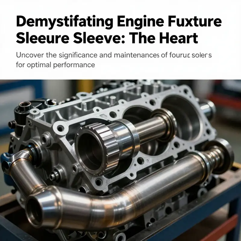
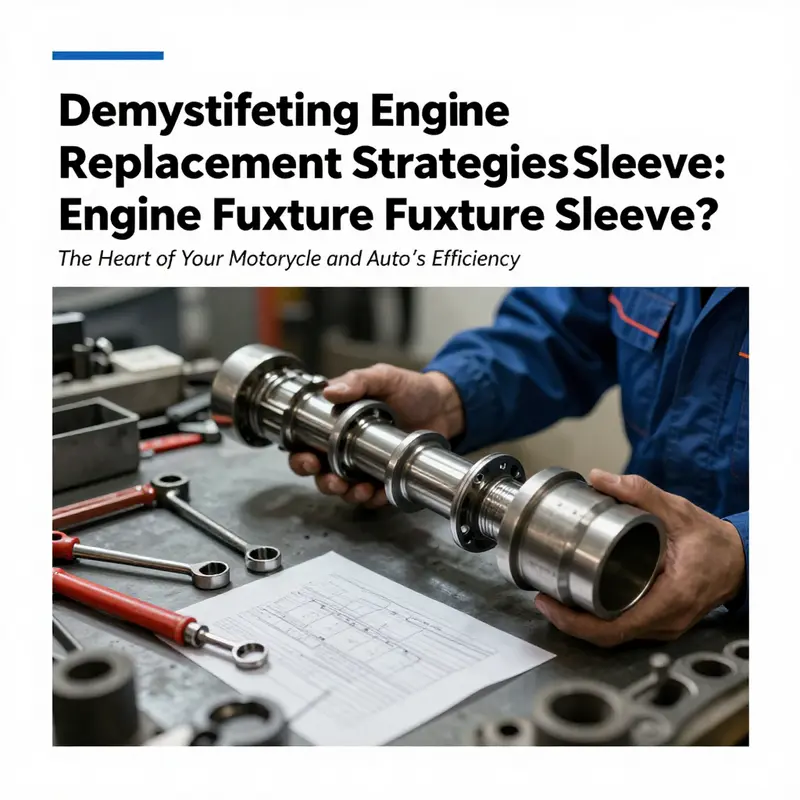
Motor vehicle performance hinges significantly on a variety of components, among which the engine fuxture sleeve plays a critical role. Often mistaken or misinterpreted, the term ‘engine fuxture sleeve’ is likely a reference to either the engine cylinder sleeve or the engine exhaust sleeve. Understanding these components and their functions is vital for motorcycle owners, auto owners, and automotive professionals alike. This article will explore the engine cylinder sleeve’s design and purpose, the pivotal function of the exhaust sleeve in performance, the materials science behind these components, the manufacturing processes involved, and effective maintenance and replacement strategies to ensure longevity and efficiency. As we delve into each chapter, we aim to provide clear insights that will empower readers to enhance their understanding, leading to better decision-making regarding vehicle maintenance and upgrades.
Sleeves That Define the Stroke: Demystifying the Engine Cylinder Sleeve and the Misinterpreted ‘Fixture Sleeve’
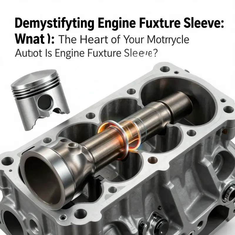
In the language of engine parts, terms travel through shops, manuals, and forums with varying precision. It is not unusual to hear a phrase like “engine fixture sleeve” bandied about, only to discover that it is not a standard component name in modern propulsion. The misnomer often points readers toward two serious but distinct ideas: the engine cylinder sleeve, also known as a cylinder liner, and the exhaust sleeve or heat-shielding sleeves that protect components around hot exhaust paths. This chapter unpacks how the cylinder sleeve fits into the engine’s living architecture, contrasts it with the exhaust-oriented sleeve, and clarifies why a single misheard term can blur the line between wear-prone internals and heat-management conduits. The goal is not to overwhelm with jargon but to provide a coherent view of how sleeves influence performance, maintenance, and longevity, which in turn helps readers interpret what they observe in an engine either on the workshop floor or in schematic diagrams. For a concise baseline on what sleeves are in general, readers can refer to a dedicated overview that discusses engine sleeves in a straightforward way.
At the core, the engine cylinder sleeve is a cylindrical lining seated inside the engine block’s bore. It is the wear-resistant inner wall against which the piston travels during every combustion cycle. The sleeve’s material choice—often cast iron or specialized steel alloys—reflects a balance between hardness to resist wear and the ability to conduct heat away from the combustion zone. The piston-ring seal remains intimately linked to this inner surface, and any deviation in the sleeve’s roundness, bore finish, or surface hardness can disrupt compression and fuel efficiency. In high-mileage or repair-oriented engines, especially large diesel units, sleeves are designed to be removable. A removable sleeve lets technicians replace the worn surface without reworking the entire block. This saves time, reduces the extent of machining, and can be a cost-effective solution for keeping a heavy-duty engine in service.
What makes the cylinder sleeve essential is not simply its hard-wearing wall but its role in maintaining the engine’s geometric fidelity. The bore must stay precisely cylindrical, with smooth, well-seated surfaces that minimize piston friction and oil consumption. The sleeve’s geometry helps establish the correct clearance between piston and wall, a tiny but critical gap that governs sealing, heat transfer, and lubrication needs. Heat management is another key function. Combustion generates substantial heat, and the sleeve participates in transferring some of that heat from the piston crown and ring zone into the engine block and ultimately toward the cooling system. In this way, the sleeve contributes to keeping piston temperatures within the design envelope, sustaining performance while avoiding thermal distortion that could undermine compression and valve timing.
It is here that maintenance philosophy comes into full view. Because sleeves can be removed and replaced, the practice of “sleeving” becomes a practical option in engines where block replacement or complete overhauls would be economically prohibitive or technically impractical. The decision to sleeve or to bore and hone a block depends on measured wear, the alloy of the sleeve, the intended duty cycle, and archival data on tolerances for that particular engine family. The process may involve precise machining, heat treatment, and careful alignment to ensure a seamless integration with the existing crankcase and cylinder head. In this light, the sleeve is less a single rigid component and more a strategic interface between the piston assembly and the engine’s thermal and lubricating systems. The potential for sleeve replacement highlights a broader principle in engine design: modularity and repairability can extend a machine’s life while reducing downtime and total cost of ownership.
If the cylinder sleeve occupies a core functional niche, the engine’s exhaust paths rely on a different category of sleeves or protective sleeves that serve heat management and routing rather than combustion surfaces. An engine exhaust sleeve, when discussed in common parlance, often describes a conduit or protective wrap around exhaust pipes that travels through engine compartments. In some configurations, a sleeve may function as a shield to prevent heat from damaging nearby wiring, hoses, or structural members. The distinction may seem subtle in everyday talk, yet it is decisive for diagnosing problems. A choked exhaust path reduces efficiency and can manifest as increased backpressure, while a protective sleeve that has worn thin or degraded may not alter the flow yet can expose adjacent components to heat-related damage or failure.
Recognizing this division is also a matter of reading the fault signs correctly. A sleeve associated with the cylinder wall, the inner lining that bears piston motion, will impact compression, ring seal, oil control, and overall efficiency if degraded. Symptoms may show up as rising coolant temperatures, oil in the combustion chamber, abnormal oil consumption, or a gradual loss of power. In contrast, a worn exhaust sleeve or heat shield might present as unusually hot engine compartments, heat-tightened wiring tangles, or exhaust leaks that are audible or detectable by scent and a drop in exhaust gas temperatures in certain zones. The diagnostic path, then, hinges on an accurate identification of which sleeve is involved. The confusion around the term itself can lead to misdirected repairs, such as attempting to reseal a cylinder bore with the wrong tooling or replacing a heat-protective sleeve when the actual issue lies in the wear pattern of the cylinder wall.
To keep the discussion grounded in practice, a quick note on terminology helps. The cylinder sleeve is the internal wall that defines the combustion chamber’s bore. Its integrity is central to the engine’s breathing and burning chemistry, and its wear dictates how well the piston rings seal and how heat is removed from the critical zone. The exhaust sleeve or protective sleeve, meanwhile, emphasizes routing and shielding rather than sealing and compression. It is not part of the catalytic cycle but is instrumental in preserving the engine’s long-term reliability by managing heat loads and exhaust flow paths.
In the larger narrative of engine maintenance and performance optimization, this distinction matters. It reframes maintenance priorities: if a mechanic notices elevated oil consumption without a corresponding exhaust leak, attention turns toward the cylinder sleeve’s wear state. If heat-related symptoms emerge in the vicinity of exhaust headers or turbocharger lines, then shielding sleeves or protective sleeves become the focal point. The practical upshot is a more precise assessment protocol that helps technicians decide whether to sleeve a block, resleeve an insert, or replace protective heat sleeves. And this clarity improves not only repair outcomes but also the engine’s lifecycle economics, because targeted interventions minimize unnecessary machining or premature component replacement.
For readers seeking a succinct primer on engine sleeves, a detailed overview exists that lays out the core concepts in accessible terms, including the distinction between the cylinder sleeve and other sleeve concepts. This resource helps reinforce the understanding that the term you hear in the shop or on a diagram matters, because it points to very different intervention strategies and performance implications. In practice, the more precise your language, the easier it becomes to locate the right replacement part, estimate service intervals, and communicate repair plans across teams.
In sum, the so-called engine fixture sleeve is not a standard designation in engine engineering. The cylinder sleeve—sometimes called a cylinder liner—functions as the wear-resistant inner wall of the cylinder, supporting piston movement, sustaining compression, and aiding heat transfer. Its counterpart—the exhaust or protective sleeve—serves to manage exhaust flow or shield components from heat, rather than participating directly in the combustion process. Mislabeling these parts risks misdiagnosis and misaligned maintenance strategies. The distinction, once understood, reveals the sleeves as two faces of the same engineering objective: to keep the engine breathing cleanly, efficiently, and safely under the most demanding conditions. For more on the precise terminology and the broader family of engine sleeves, see the dedicated overview linked here, and for a broader technical context, consult established references such as the Cylinder liner page. See also the internal link for a concise primer on engine sleeves: What are engine sleeves?. And for a broader external reference, Cylinder liner – Wikipedia.
Guardians of the Gases: How the Exhaust Manifold Heat Shield Shapes Engine Performance
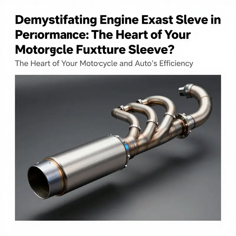
Engine jargon travels quickly through shop bays and forums, and a misspelled or misheard term can drift into the maintenance schedule and cause confusion. The phrase “engine fuxture sleeve” isn’t a recognized component in standard catalogs. In practice, the sense of such a term points to parts that guard heat or endure the harsh environment around the exhaust and cylinder bores. Two sleeves commonly appear in discussions of performance and reliability: the cylinder sleeve, which lines the combustion bore, and the exhaust sleeve, which protects heat-sensitive components and, in many configurations, helps manage how exhaust energy moves away from the engine. The distinction matters because each sleeve serves a different purpose: one protects the engine’s core from wear, the other guards heat and can influence how efficiently exhaust gases depart the cylinders. Yet when the language shifts from sleeves to shields, a clearer picture emerges of how heat control intertwines with performance, durability, and safety. The element at the heart of this broader conversation is the exhaust manifold heat shield, or its insulation variant—often described in practical terms as an insulation sleeve around the manifold. This shield is not merely a cosmetic cover; it is a carefully engineered barrier designed to contain heat, protect nearby components, and subtly tune the engine’s thermal behavior to favor performance. A good heat shield does more than keep things cool. It preserves the delicate balance of temperatures that drive combustion efficiency and exhaust flow, especially in modern engines where turbocharging and advanced fuel-management strategies reward consistent, high-temperature exhaust gases.
What follows is a cohesive look at the role of this protective layer, the materials that make it possible, and the ways it affects the engine’s performance landscape. The shield’s core function is thermal insulation and heat containment. By wrapping the hot exhaust manifold, the shield reduces radiant heat radiating into the engine bay. This containment translates into several practical benefits. First, higher exhaust gas temperatures within the exhaust tract can improve flow. When exhaust gases exit more quickly and at elevated temperatures, the scavenging effect—where spent gases are pulled out of the cylinders more efficiently—can improve. This is particularly advantageous for turbocharged engines, where turbine performance is sensitive to the energy carried in the exhaust. By minimizing heat loss to the surrounding metalwork and air, the exhaust gas retains its energy longer as it travels toward the turbine, contributing to quicker spool and improved turbo response. The shield effectively reshapes the thermodynamic boundary of the engine bay, nudging the system toward a more favorable balance between power and efficiency.
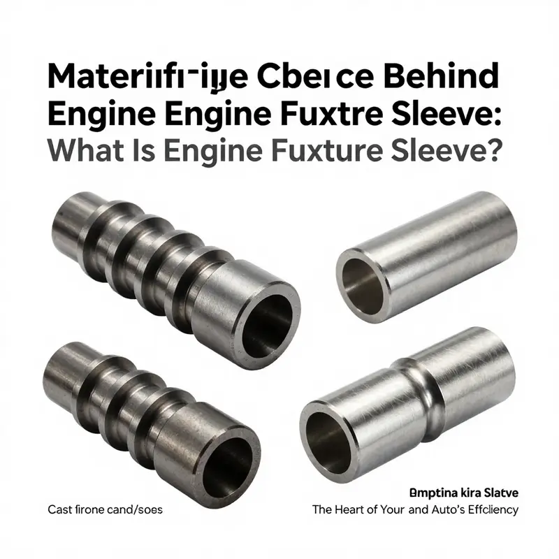
The materials that realize this shielding are as varied as the engines themselves. The core requirement is steadfast resistance to high temperatures and rapid thermal cycling. Ceramic-coated fiberglass blankets have long been a staple, offering high-temperature tolerance and a compact form that wraps snugly around the manifold. Silicone-based sleeves provide another approach, combining flexibility with durable heat resistance. In heavy-duty or high-stress applications, metal alloys with ceramic coatings deliver enhanced longevity and mechanical robustness. The choice among these options is not merely a matter of heat resistance; it also concerns ease of installation, serviceability, and how the chosen material interacts with nearby components during maintenance. The goal is to avoid heat-induced degradation of rubber hoses, vacuum lines, electrical wiring, and plastic ducting that nestle close to the manifold. When a sleeve or shield is well designed, it creates a cooler microenvironment around these delicate pathways, mitigating the risk of insulation failure, melting, or softening that could compromise performance or safety. In this sense, the shield acts as a preliminary line of defense, preserving the integrity of the engine’s sensory and control networks as well as its most vulnerable plumbing.
Beyond protection, the heat shield contributes to a more stable overall thermal profile in the engine compartment. A cooler, better-contained manifold helps reduce heat soak into the intake system and adjacent components. In turn, this promotes more predictable air intake temperatures and sensor readings, which matter for fuel metering and ignition timing. When sensors measure cooler intake air and the control unit receives consistent signals, the engine runs with fewer idle fluctuations and more reliable performance across a range of operating conditions. The shield’s presence also has a quiet, if modest, effect on acoustics. While not a primary function, some shielding designs dampen the higher-frequency noise produced by the manifold’s heat and the exhaust flow, contributing to a marginally quieter under-hood environment.
From a safety standpoint, the heat shield is indispensable. Exposed metal surfaces near the exhaust manifold can become blistering hot and pose a burn risk to technicians during service. The shield reduces those hotspots, making routine inspections and quick repairs safer. In addition, by keeping heat in the exhaust pathway, the shield reduces the chance that heat will affect plastics, hoses, and wiring that could otherwise degrade and create leaks or electrical issues. The layered protection offered by a heat shield thus translates into fewer in-field failures and longer service intervals, especially in engines that operate at elevated temperatures for extended periods—such as those in performance applications, heavy workloads, or climate-strained environments.
To connect the concepts with practical understanding, consider how heat management intersects with maintenance planning. Visual inspection remains the frontline test for shield condition. A seasoned technician looks for signs of worn or blistered insulation, visible gaps in coverage, or rubbed-through areas where metal has abraded against the sleeve. Repairs or replacements are typically straightforward but must preserve the seal around the manifold and prevent heat hotspots elsewhere. In many cases, a damaged shield correlates with heat-related wear in adjacent components, so a shield inspection can serve as a diagnostic cue for broader maintenance needs. For readers curious about sleeves in general and how they fit into engine life, a helpful background resource is What are engine sleeves? which explains the broader category of sleeves and how they relate to engine blocks and wear management. What are engine sleeves?
Of course, the narrative around the exhaust heat shield sits alongside the broader engine architecture. Cylinder sleeves, for example, are integral to the combustion process and the durability of the cylinder bore, whereas the exhaust shield is a post-burn, heat-management feature. When engineers design an engine for performance and longevity, they consider the interplay between bore wear resistance, heat transfer, and exhaust efficiency. Each sleeve type contributes to a different aspect of the engine’s life cycle, and understanding their roles helps technicians diagnose issues with clarity and confidence. The shield’s impact on performance becomes most evident in how it preserves the conditions that allow exhaust systems to function efficiently, particularly under demanding loads or high-Gamma driving scenarios where backpressure and scavenging dynamics are finely tuned by the exhaust layout and thermal envelope around it.
Beyond the specific materials and functions, the broader takeaway is that heat management in the exhaust region is a quiet but powerful amplifier of performance potential. It is a reminder that the engine is a system in which every component, from the cylinder walls to the exhaust manifold’s exterior, must operate within a carefully controlled thermal corridor. When that corridor is well managed, the engine can sustain higher exhaust gas temperatures, improved flow characteristics, and more reliable operation under stress. The result is not a single dramatic gain but a chain reaction: better scavenging, more efficient energy transfer, reduced heat-induced wear, and reinforced safety. In this way, the exhaust manifold heat shield becomes a small but mighty contributor to the bigger picture of engine efficiency and resilience. As readers move forward, the conversation can broaden to how these protective strategies align with cylinder sleeve designs and the enduring question of how sleeves—whether wet, dry, or sleeved in the block—interact with a holistic approach to engine durability and performance.
For readers seeking a deeper dive into sleeves in general, exploring the broader sleeve ecosystem and how it interacts with performance can unlock a fuller understanding of engine design. As you navigate these concepts, keep in mind the shield’s critical role: not merely a barrier between hot gases and fragile components, but a strategic partner in maintaining the integrity and efficiency of the entire powertrain. External resources on heat shields, such as general explanations of heat shields and their purposes, can provide useful context for the broader engineering principles at work. For further reading, see https://en.wikipedia.org/wiki/Heat_shield.
Injecting Precision: The Material Science Behind Engine Fuel Injector Tube Sleeves
In the realm of engine design, the term engine fixture sleeve can spark confusion, especially when it drifts toward the visible parts like cylinders or exhaust paths. Yet a quieter, equally vital component exists at the heart of modern diesel fuel delivery: the fuel injector tube sleeve. This sleeve is not a mere housing; it is a precision locus where alignment, sealing, heat transfer, and high-pressure tolerance converge. It sits inside the cylinder head, closely surrounding the injector body, and it must hold its shape and position under repeated thermal cycles, fuel exposure, and the near-rupture pressures of injection events. The sleeve’s job is to ensure that the injector remains properly oriented, that fuel is delivered to the combustion chamber with minimum leakage, and that heat from combustion and from the injector itself is managed so nearby metal does not overheat or warp. In a sense, the injector tube sleeve is a bridge between fluid dynamics and thermomechanical stability, a tiny but determinative piece that influences efficiency, emissions, and long-term reliability. For a broader view of sleeving concepts, it helps to explore how sleeving is discussed in general terms; see What Sleeving an Engine Means for a solid overview of sleeving concepts before returning to the specifics of injector sleeves.
The injector tube sleeve fulfills several interlocking roles. First, it serves as a precisely machined bore that houses the injector nozzle and seat, guiding the injector’s axis with tight tolerances. Any misalignment can translate into faulty fuel spray patterns, uneven combustion, or fuel leakage along injector seals. The sleeve’s inner diameter is held to strict tolerances so the injector can seal reliably against the head gasket or integrated seals, while its outer geometry integrates with the surrounding cylinder head passages and cooling channels. Second, the sleeve plays a role in thermal management. Diesel combustion generates substantial heat, and the injector housing itself becomes a heat source. A sleeve made from a material with high thermal conductivity can help spread heat away from the injector seat, reducing hot spots that could accelerate wear or alter spray characteristics. This is not about cooling the entire engine, but about maintaining a stable microenvironment around the injector and its seat. Third, the sleeve contributes to chemical resilience. Diesel fuel, combustion byproducts, and cooling fluids present a corrosive, aggressive environment. The sleeve must resist corrosion and resist wear through cavitation, erosion, and repeated high-pressure cycles. Thus, material choice is a dance between conductivity, strength, corrosion resistance, and compatibility with the sealing system that keeps fuel from leaking past the injector seal into the combustion chamber or the head gasket.
Materials selected for injector sleeves reflect this balancing act. Copper-based alloys are popular for their exceptional thermal conductivity, which helps to dissipate heat efficiently away from the injector zone. This quick heat transfer smooths temperature gradients that could otherwise cause dimension changes and seal failures over many cycles. Copper alloys also offer good wear resistance and can be engineered for corrosion resistance in the harsh diesel environment. In practice, the sleeve may be manufactured from copper alloys or other high-conductivity metals that support stable dimensions even as temperatures swing between cold starting and hot running. The exact alloy choice hinges on the engine family, the expected duty cycle, and the design intent—whether the emphasis is on maximizing heat dissipation, ensuring long-term wear resistance, or achieving the tightest possible tolerances around the injector seat. It is not unusual for engineers to specify additional alloying elements or surface treatments to optimize surface hardness and reduce friction at the injector contact surface.
Dimensional stability under thermal cycling is another cornerstone of sleeve performance. When an injector is fired, heat flows into the surrounding head material and the sleeve, setting up a differential expansion pattern between components that must be carefully managed. If the sleeve expands too much or too little relative to the injector body or the head, seals can fail or the injector can shift, altering spray geometry. The engineering challenge is to align coefficients of thermal expansion across members so tolerances remain within spec during start-up and steady operation. This is where manufacturing precision becomes essential. The sleeve is typically produced with meticulous surface finishes and tight bore geometry, followed by finishing steps such as honing or lapping to achieve the exact cylindrical form. Surface treatments may be applied to reduce galling and wear where the injector seals interface with the sleeve, further extending service life.
From a manufacturing perspective, injector sleeves exemplify how precision machining and materials science intersect. The process begins with selecting a billet or tube stock that matches the chosen alloy. Next comes turning to establish the outer profile and bore, with strict alignment between bore axis and head geometry. The inner bore receives a finish that supports seal integrity while resisting wear from the injector’s needle and nozzle seat. Heat treatment may follow to reach a balance of hardness and toughness, helping the sleeve resist micro-wear and thermal fatigue. Finally, a finishing pass achieves the demanded roughness and dimensional accuracy. In some designs, coatings or surface hardening are applied in targeted regions to protect the seating surface from wear while preserving the thermal conductivity benefits of the base metal. The result is a sleeve that remains faithful to its position through tens of thousands of injections, while resisting the creeping dimensional changes that can accompany long service life.
The injector sleeve also has to contend with sealing architecture. The injector itself is typically sealed to the head through a combination of O-rings, crush washers, and seating surfaces. The sleeve must establish and maintain a stable seating plane for these seals. Any deformation or unevenness at the seating surface can compromise the seal and create a path for fuel leakage, which not only wastes fuel but also can create safety and emissions concerns. Therefore, the sleeve’s surface finish quality, flatness, and roundness are as important as its material chemistry. These factors work together with the injector’s own design to keep pressures high—at times several thousand pounds per square inch—without sacrificing precision or reliability. The real-world consequence of this integration is improved spray consistency, better combustion, and reduced particulate emissions over the engine’s life.
Operational longevity is the ultimate test for injector sleeves. Diesel engines operate under harsh conditions: rapid heating and cooling, corrosive fuel blends, and continuous injection cycles. A sleeve that holds its form over thousands of cycles minimizes maintenance requirements and reduces the risk of injector misalignment. In service, technicians watch for telltale signs of sleeve trouble: shifting injector alignment, uneven spray patterns, or fuel leaks at the injector seat. When such symptoms appear, it may indicate that the sleeve has begun to wear or lose dimensional stability, prompting inspection and eventual replacement. The decision to replace is guided by the balance of cost, downtime, and the potential impact on engine performance and emissions. Regular inspection and adherence to maintenance schedules are essential for preserving the injector’s role and, by extension, the engine’s overall efficiency.
Within the broader landscape of engine sleeves, the injector tube sleeve is distinct from the cylinder sleeve, itself a wear-resistant wall that houses the piston’s travel in the combustion bore. The cylinder sleeve must withstand the daily assault of piston rings, combustion heat, and occasional honing, while the injector sleeve must contend with fuel exposure, high injection pressures, and the need for exact injector alignment. This distinction underscores why the injector sleeve deserves dedicated material science attention, even as its performance remains inseparable from the engine’s larger thermal and mechanical ecosystem. For readers seeking a concise, general take on sleeving concepts that complements this discussion, the linked overview provides a helpful primer on how sleeving relates to engine architecture, while keeping the focus on the specific accuracy required by injector sleeves here.
As the industry continues to refine diesel fuel delivery, the emphasis on material science around injector sleeves will only grow. Engineers balance heat transport, wear resistance, chemical compatibility, and precision to deliver reliable, efficient, and cleaner engines. The sleeve becomes a strategic component: a small part with outsized influence on how the injector seats seal, how heat is managed around the nozzle, and how consistently the engine can deliver fuel in the exact spray pattern required for optimal combustion. This integration of materials, geometry, and surface engineering demonstrates how even a seemingly modest component can govern the higher-order performance traits of the engine—from fuel economy and power to emissions and longevity.
External resource for further reading provides a broader sense of copper-based injector sleeves in diesel applications: https://www.made-in-china.com/products/675442c1.html. For a targeted overview of sleeving concepts and how injector sleeves fit into the broader engineering narrative, consider the internal discussion at What Sleeving an Engine Means. The dialogue between general sleeving principles and the specifics of injector sleeves helps illuminate why material selection and surface engineering matter so profoundly in modern combustion engines.
The Quiet Backbone of Precision: How Engine Fixture Sleeves Shape Cylinder Bore Quality

In the language of modern engine production, the term engine fixture sleeve rarely turns up in the shop manual for drivers or even service technicians. Yet it works as a quiet backbone of precision. The phrase often emerges through the lens of design engineers and machinists during the planning of a new assembly line. What seems like a minor accessory actually governs the alignment, stability, and repeatability that keep manufacturing costs predictable and engines consistent. In this chapter, we untangle what an engine fixture sleeve is, how it differs from the cylinder liner that houses the piston, and why it matters for the integrity of every bore we machine. The discussion centers on the sleeve as a fixture element, not a live part inside the engine.
At its core, the primary function of an engine fixture sleeve is to maintain dimensional accuracy and tolerance control during critical stages of machining and assembly. It acts as a precision guide or support that holds or positions other parts with repeatable exactness. During boring, the sleeve ensures the cutter remains concentric with the intended axis, so the bore diameter and roundness meet spec. During honing, it stabilizes the workpiece to achieve the intended surface finish. When installing cylinder liners, it helps align the liner with the block so that the bore’s true axis remains intact. In testing or fixture-based assembly stands, the sleeve provides a reliable reference point for pistons, crankshafts, and valves, allowing quick checks of geometry.
Manufacturers design fixture sleeves as components of a larger fixture system, which may include locating pins, clamps, hydraulic actuators, and adjustable stops. The cooperation of these elements determines how quickly a part can be loaded, clamped, and released, while keeping tolerances tight enough to pass the most stringent quality gates. The sleeve itself must resist deformation under clamping forces and heat, which means material choice and surface integrity are crucial. The most common raw materials are hardened steels or high-grade tool steels for their wear resistance, while some lighter or heat-dissipating setups may employ aluminum alloys with careful thermal management. To achieve their exacting dimensions, manufacturers rely on CNC turning for rough shaping, followed by precision grinding to reach the final diameter and straightness, and sometimes broaching to create internal features that standard tools cannot.
Surface finish and geometry are not afterthoughts; they are the lifeblood of the fixture sleeve’s utility. The bore inside the sleeve must be true to size within a few micrometers in many cases, and the external profile must align with mating fixtures with minimal runout. This is where honing and grinding play critical roles, refining both form and surface texture. In some installations, the fixture sleeve doubles as a conduit for hydraulic lines or locating features that interface with clamps. The result is a system that supports rapid loading while preserving the delicate tolerances that govern cylinder wear in service. When liners are pressed or pressed-in, this precision reduces the risk of misalignment, piston scuffing, or uneven bore glazing that would degrade engine performance later on.
Beyond the machining bay, fixture sleeves influence assembly quality in ways that ripple into performance and longevity. If the sleeve guides a liner with poor concentricity, the entire engine assembly risks offsetting the bore relative to the piston stroke. Over many cycles, such a misalignment translates into reduced volumetric efficiency, uneven heat distribution, and accelerated wear. Conversely, a well-calibrated fixture sleeve helps ensure every liner sits in exact relation to the crank axis. That alignment supports consistent piston travel, even ring seal, and predictable compression. The reliability of the production process reduces rework, scrap, and the downtime associated with retests. In this light, the sleeve becomes less a component and more a factory discipline: a standard that codifies precision at every step.
From a manufacturing standpoint, the production workflow for fixture sleeves hinges on tight process control and traceability. CNC turning sets the rough geometry, producing the correct outer diameter, length, and shoulder geometry for integration with fixtures. Grinding then nails straightness and roundness, and any internal pockets or grooves are chased with careful broaching if needed. Surface treatments like nitriding or chrome plating may be applied to increase wear resistance and reduce corrosion in demanding environments. Coatings can also tailor friction characteristics to minimize seizing during clamp cycles. Metrology follows, with governors for temperature, humidity, and gage calibration to ensure that every sleeve leaving the shop can be trusted to perform identically on the line. This sequence, though technical, is the spine of consistent engine assembly.
Material science underpins every choice here. Hardened steels provide longevity under repeated contact and high clamping forces. Tool steels resist deformation during high-speed machining. In some lightweight lines, engineers opt for aluminum alloys when heat transfer or weight savings take priority, but these require careful design to avoid deformation under load. The surface hardness, case depth, and residual stress from heat treatment influence how the sleeve behaves under cyclic machining and assembly. It is not merely about dimensions; it is about how the sleeve accepts and distributes forces during press fits, how it copes with the temperatures of machining, and how it preserves the integrity of the axes it supports throughout the life of the production line. The best sleeves tolerate minor misalignments without propagating error, acting as a forgiving anchor for precise work.
Engineering standards anchor this practice. OEM guidance and industry specifications shape the tolerances, surface finishes, and inspection routines that define a successful fixture sleeve program. Dimensional checks, concentricity tests, and material certifications accompany each batch, while change control records trace any deviation back to its source. The discipline of documentation ensures that a shift in tooling or a new batch of raw stock does not silently erode the quality of the bore. As with most precision manufacturing, the lifecycle of a fixture sleeve extends beyond any single job. It is inspected, repaired, and, when necessary, replaced with anticipation rather than crisis. Such rigor reduces surprises on the shop floor and supports the long-term reliability of the engines that will eventually wear those bores during their service life.
To clarify terminology for readers navigating the broader literature, the fixture sleeve discussed here is a manufacturing accessory, distinct from the cylinder liner or exhaust sleeve that forms part of the engine’s living hardware. Mixing them can cause confusion when diagnosing issues or planning maintenance. The fixture sleeve does not ride within the combustion chamber and does not participate in heat transfer during engine operation. Its value lies in enabling repeatable production of the exact bore geometry that the engine will later rely upon. For readers who want a more direct comparison or who are mapping terms across sources, a concise overview can be found by exploring resources that explain what engine sleeves are and how they relate to different sleeve types. This grounding helps engineers and technicians maintain clarity as they work across the design-build-test continuum. What are engine sleeves?
Further reading offers practical context on how sleeve concepts intersect with modern machining strategies and the broader ecosystem of engine manufacturing. When teams discuss tolerances, coatings, or fixture alignment, they are reframing a familiar problem in terms of process control, measurement, and repeatability. For those seeking a reliable external perspective, an accessible guide on engine sleeves can deepen understanding without diving into obscure jargon. External reference: https://www.carinterior.com/engine-sleeve-guide-how-to-choose-the-right-type/
null
null
Final thoughts
In summary, the engine fuxture sleeve is a vital component that significantly influences the efficiency and performance of vehicles. Understanding both the engine cylinder sleeve and the exhaust sleeve enhances not only vehicle maintenance strategies but also ensures owners can make informed decisions regarding repairs and upgrades. By appreciating the material properties, manufacturing processes, and effective maintenance techniques, both motorcycle and auto owners can extend their vehicles’ longevity and efficiency. This knowledge is crucial in optimizing performance and ultimately elevating the driving experience.