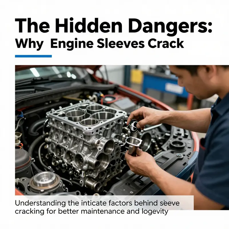
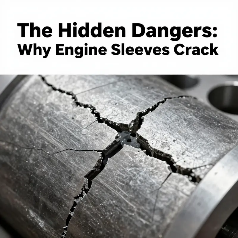
Engine cylinder sleeves play a critical role in the performance and durability of internal combustion engines. However, they are not immune to failure, specifically through cracking—an issue that poses significant risks to motorcycle and automobile owners alike. Understanding the multifaceted reasons why engine sleeves crack is essential for ensuring vehicle reliability and extending engine life. This article delves into the primary root causes of sleeve cracking, including thermal stress, improper installation, cavitation erosion, and material fatigue. By exploring each chapter, readers will gain comprehensive insights into how operational factors contribute to engine sleeve failures, enabling better maintenance practices and informed decisions in service and parts distribution.
null
null
null
null
How Cavitation Erosion Starts Small and Ends with Cracked Engine Sleeves
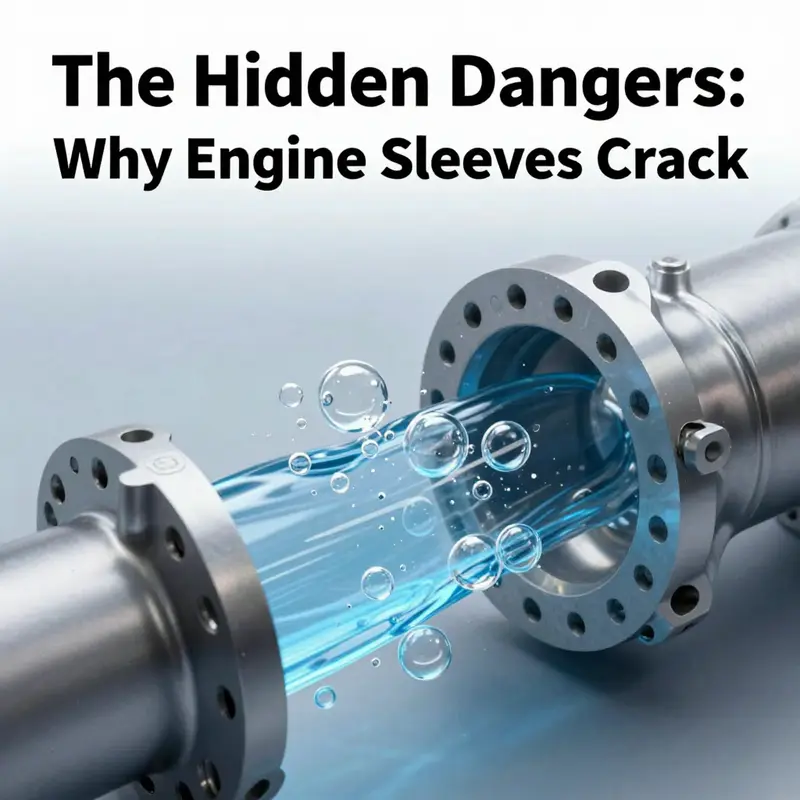
Cavitation is a quietly destructive process. In wet-sleeve engines, it begins with tiny vapor bubbles and ends with metal loss, structural weakening, and ultimately cracked sleeves. Understanding this progression clarifies why some failures look sudden but are the result of long-term erosion paired with normal engine stresses. This chapter follows that path. It explains how bubbles form, where they attack, how damage grows, and what interactions with thermal and mechanical loads cause a crack to appear.
At the core, cavitation is a pressure phenomenon. When local coolant pressure drops below its vapor pressure, tiny bubbles form. These bubbles travel with the flow into higher-pressure regions and collapse violently. Each collapse delivers a focused micro-jet and shock wave to the sleeve surface. One implosion alone is harmless. Repetition is not. Thousands of implosions concentrate energy on microscopic areas, gradually removing material. The surface first shows pits so small they are invisible to the naked eye. Over repeated cycles, those pits deepen and coalesce. Eventually the liner wall thins enough that ordinary engine forces become capable of opening a crack.
Some design and operating factors make cavitation worse. Wet liners are surrounded by moving coolant and are exposed to pressure swings produced by piston motion and combustion. Areas with turbulent flow, sharp edges, sudden cross-sectional changes, and proximity to pump outlets see the most violent cavitation. Ports or grooves cut into the liner for coolant passages can create local vortices. Even narrow gaps between the sleeve and block cause pressure fluctuations. Where the sleeve has thin sections or machining marks, cavitation finds a weaker target. Manufacturing features that leave residual tensile stress or micro-roughness amplify the effect.
Coolant dynamics also shape cavitation risk. Higher flow velocities lower local pressure and increase the likelihood of bubble formation. Rapid pressure recovery zones then produce forceful bubble collapse. Air entrained in coolant or improper coolant temperature control further destabilizes pressure. Contaminated or degraded coolant changes vapor pressure and reduces cavitation resistance. In short, coolant that cannot maintain stable hydraulic conditions lets cavitation develop and persist.
Material matters. Common sleeve materials—cast iron and certain steels—resist wear differently. Cast iron resists many forms of wear but is vulnerable to cavitation pitting if its microstructure or surface hardness is inconsistent. Some alloys develop micro-cracks from repeated fatigue under the influence of cavitation. Manufacturing defects like porosity or inclusions become focal points. Where micro-voids exist beneath the surface, imploding bubbles can cause localized tensile stress that opens those voids into surface defects. Over years of service, these sites enlarge much faster than surrounding metal.
Cavitation does not act in isolation. It lowers wall thickness and roughens the surface. Those changes increase local thermal gradients during operation. A rough, pitted surface traps hot spots and changes heat transfer locally. That creates uneven thermal expansion. Thermal cycling then interacts with the thinned wall to initiate and propagate cracks. Combustion pressure and mechanical loading from piston and rod forces apply alternating stress to the weakened region. What began as microscopic pitting evolves into a fatigue crack that grows with each cycle. In many real-world failures, neither cavitation nor thermal or mechanical fatigue alone was enough to cause a sudden breach. Their combination was.
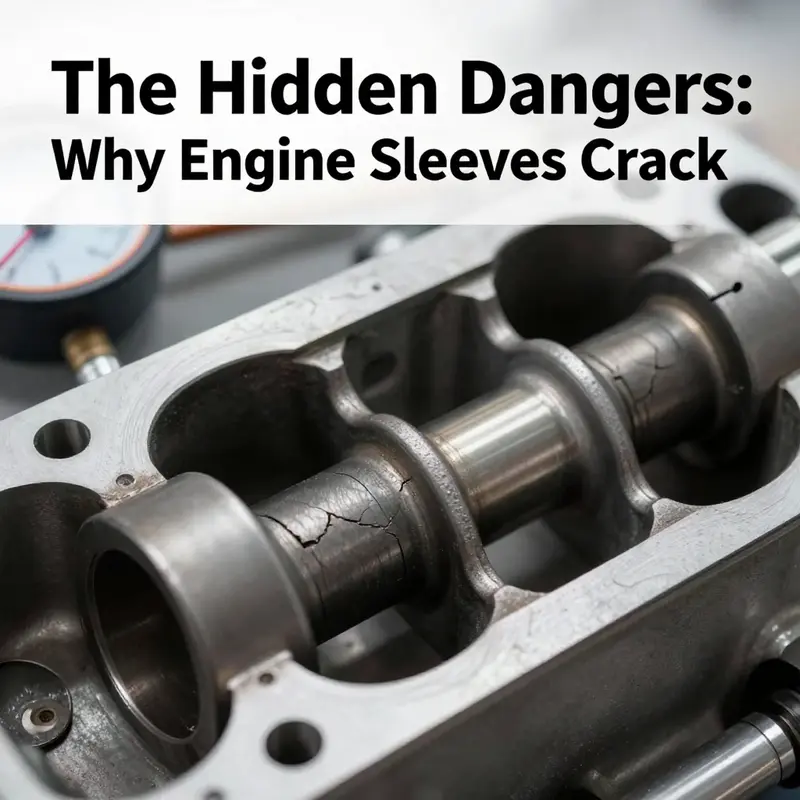
The progression from pitting to cracking typically follows a predictable path. The first visible sign is small pits on the coolant side of the liner. These pits expand and merge, producing cup-shaped cavities. Surface roughness climbs, and the liner’s effective thickness drops. At some point a stress concentration forms at an edge of a pit or at a transition between eroded and sound metal. Under repeated load cycles, a fatigue crack nucleates at that concentration. Once a crack establishes, it can spread circumferentially or axially. Circumferential cracks are dangerous because they can free a sleeve section, allowing coolant intrusion. Axial cracks may leak coolant into the combustion chamber or the crankcase.
Detecting cavitation damage early is possible but requires attention. Visual inspection during rebuilds or service will reveal pitting on the coolant side. Borescope checks through coolant passages sometimes show early pits. Sound signatures can change; cavitation often produces a distinct noise from the head area. Coolant loss without visible external leaks points to internal erosion. Pressure testing and dye penetrant tests may highlight breached liners. Ultrasonic thickness measurements track wall thinning without disassembly. Regularly scheduled inspections and fluid condition monitoring make these methods effective in catching cavitation before it produces a crack.
Mitigation combines design, materials, and maintenance. On the design side, smoother coolant paths reduce turbulent zones. Eliminating sharp edges and creating gradual transitions in passages reduces local pressure drops. Increasing local sleeve thickness in historically vulnerable zones raises the threshold for breakthrough. Some manufacturers adopt anti-cavitation geometries around ports and use baffles to manage flow. Coatings and surface treatments improve resistance. Hard-facing and case-hardening raise the surface hardness the implosions must erode. Advanced surface engineering can blunt micro-jets and delay pit formation.
Material selection and processing also help. Denser, more uniform alloys resist cavitation longer. Avoiding porosity and inclusions during casting reduces attack points. Heat treat cycles that produce a more homogeneous microstructure and controlled residual stresses lower crack nucleation tendency. In service, maintaining coolant chemistry preserves the fluid’s vapor pressure and cavitation threshold. Using the correct coolant type, keeping contamination low, and following recommended replacement intervals matter more than many operators appreciate. A well-maintained cooling system reduces both bubble formation and the corrosive effects that amplify cavitation damage.
Operational practice plays a large role. Excessively high pump speeds or incorrect thermostat operation can increase flow-induced pressure swings. Air trapped in the cooling system promotes bubble formation. Ensuring proper filling and bleeding of the coolant system removes this risk. Avoiding extreme transient loads reduces sudden pressure changes that accelerate cavitation growth. Where engines operate under severe duty, more frequent inspections of liners and coolant condition pay off. When cavitation is suspected, immediate action to stabilize coolant parameters and reduce operating stress can halt further damage while planning repairs.
Repair strategies depend on damage extent. Minor pitting can sometimes be blunted by resurfacing or by applying a corrosion-resistant coating. Severe thinning often requires sleeve replacement. Wet liners are replaceable, and that replacement can correct both geometry and material deficiencies. In some designs, sleeves are available in upgraded materials with better cavitation resistance. Repair without addressing the root cause invites repeat failure. Fixes must include coolant system diagnostics, flow-path smoothing, and attention to coolant chemistry to be durable.
The most severe consequence is sudden coolant intrusion. When erosion penetrates the full liner thickness or when a crack connects coolant passages to the combustion chamber, coolant floods cylinders. That can cause misfires, loss of compression, and hydrolock in extreme cases. Coolant in the combustion chamber also causes rapid corrosion and may lead to head gasket failure or catastrophic cylinder-head damage. Because cavitation damage accumulates, these catastrophic events usually follow a long period of undetected degradation. That is why inspection and preventive action are essential.
Case studies and technical analyses show a consistent pattern. Engines subject to high coolant flow velocity, turbulent passages, or poor coolant maintenance show higher rates of sleeve erosion. Design fixes, such as smoothing ports and improving coolant flow distribution, reduce incidents. Surface treatments extend service life in many fleets. Research confirms that preventing cavitation is far cheaper than repairing its consequences. For a technical study that examines real-world failures and quantifies these mechanisms, see the detailed analysis at https://doi.org/10.1115/1.3230350.
Finally, treating cavitation as part of a systems problem yields the best results. Designers, material engineers, and maintenance crews must share responsibility. Simple procedures—keeping coolant clean, maintaining correct temperatures, and eliminating air—have outsized value. Thoughtful design reduces the initial conditions that allow cavitation to begin. Together, these steps transform an unpredictable failure mode into a manageable maintenance challenge. For engineers and operators focused on preventing cracked sleeves, that coordinated approach is the most effective path forward.
For practical guidance on how wet-sleeve engines handle heat and coolant flows, consult this resource on wet-sleeve engine thermal management: wet-sleeve engine thermal management.
The Quiet Fracture: Material Fatigue, Thermal Cycles, and the Cracking of Engine Sleeves
Material fatigue is the hidden driver behind many failures in engine hardware, and cylinder sleeves are a clear echo of that truth. In the heart of an internal combustion engine, the sleeve sits as a thin-walled guardian, lined with metal that must endure heat, pressure, and mechanical wear for thousands of cycles. Over time, the very forces that power a machine—the rapid heating from a controlled combustion event and the subsequent cooling as the engine sheds heat—set up a relentless rhythm. Each cycle inflicts a tiny, almost imperceptible amount of plastic and elastic strain within the sleeve’s crystal lattice. When these strains accumulate, especially near points where the material is naturally weaker or where the geometry concentrates stress, microscopic cracks creep and multiply. If the operating conditions persist, these microcracks can become a network of flaws that compromise the sleeve’s ability to contain pressures, resist deformation, and maintain a proper seal with the piston and surrounding components. The result, often only visible long after the damage begins, is cracking, loss of compression, coolant intrusion, or even catastrophic failure. The story of cracking is thus not a single event but a chronic process of damage accumulation driven by fatigue under demanding thermal and mechanical conditions.
To understand why sleeves crack in the first place, it helps to view fatigue not as a single weakness but as a continuous dialogue between material properties and operational reality. Engines are designed to transform chemical energy into motion, but they do so through cycles that repeatedly stress every component. The sleeve, in particular, is subjected to a sequence of extreme temperature swings: the moment the fuel-air mixture ignites, the sleeve’s inner surface soaks up heat from the combustion chamber while the outer surface is exposed to the cooler metal of the block and the surrounding environment. The differential heating generates thermal gradients across the sleeve wall. The metal expands, then cools as the cycle ends and the coolant absorbs heat. This daily cadence, repeated hundreds of thousands of times in a typical component’s life, taxes the sliding relationship between sleeve and block. The geometry of the sleeve—its edges, bores, and interfaces—works with the physics in a way that concentrates stress, creating hot spots where microcracks are most likely to initiate.
The core mechanism of fatigue, as described in materials science, is the nucleation and growth of microscopic cracks under cyclic loading. It begins at locations of stress concentration—grain boundaries, inclusions, microstructural defects, or the interface where the sleeve meets the block. Persistent slip bands, a feature of crystalline metals under repeated shear, can form in regions of high local strain. These bands become the favored paths for crack initiation. Once a crack has formed, its growth rate depends on factors such as the amplitude of the loading, the temperature, and the presence of environmental or chemical interactions. In engines, the crack may grow slowly at first, barely perceptible to the naked eye or through simple compression tests, but as cycles accumulate, the crack lengthens until it reaches a critical size where rapid propagation and failure become likely. This progression—initiation, slow growth, rapid propagation—describes much of what we observe as sleeve cracking in aging or heavily stressed engines.
As a result, much of the lifetime management of engine sleeves hinges on controlling the variables that feed fatigue. One primary driver is thermal stress. The repeated heating and cooling impose cyclical mechanical strains that, even if each cycle is below the material’s static strength, can cause long-term microstructural damage. Overheating exacerbates this by broadening the temperature swing and intensifying thermal gradients. If, for example, a cooling system falters, the sleeve wall may experience sharper temperature spikes and slower cool-down periods. The consequence is an acceleration of fatigue damage, especially near the sleeve’s inner and outer edges where temperature gradients are steepest. In practical terms, sustained overheating or sudden temperature surges create conditions under which PSBs, or persistent slip bands, more readily form and become crack nuclei. Hence, maintaining a stable thermal environment becomes not just a matter of efficiency but a crucial fatigue countermeasure. For readers seeking a concise primer on what engine sleeves are and how they function, a quick primer can be found at What are engine sleeves?.
Fatigue does not act in isolation. A sleeve’s susceptibility to crack growth is strongly influenced by how well it is manufactured and how precisely it is installed. Even if the base material is highly alloyed and designed for high-temperature endurance, small defects introduced during production—voids, porosity, nonuniform composition—still act as weak points. When the sleeve is improperly installed, edge misalignments or improper torque on the head bolts can introduce local stress concentrations that serve as preferred crack initiation sites. In such cases, the fatigue process can start from pre-existing flaws or from artificial stress raisers created during assembly. The result is that fatigue is not merely a consequence of time and use but a culmination of design, fabrication, and service practices. This is why preventive maintenance that targets installation integrity and assembly quality is as important as choosing a robust alloy. It is also a reminder that fatigue interacts with the other drivers in the spectrum of sleeve cracking, such as cavitation erosion in wet-sleeve designs and corrosion in aggressive cooling environments. In wet-sleeve systems, cavitation arises when coolant pressure fluctuations near the moving piston induce tiny vapor cavities that implode near the sleeve surface, eroding material in a manner that weakens the wall and opens the door for fatigue cracks to propagate sooner under load. In the broader picture, fatigue is the thread that ties engine cleanliness, coolant quality, timing and calibration, and component fit into a single framework of durable performance.
The fatigue story also depends on the material’s own history. While modern sleeves may use high-strength alloys with good creep resistance and thermal stability, all metals experience fatigue under the right cyclic conditions. The microstructure—grain size, phase distribution, the presence of inclusions—dictates how easy or difficult it is for a crack to start and to grow. Under cyclic thermal loads, grain boundaries can become sites of stress accumulation, encouraging dislocations to move in persistent patterns that form PSBs. As the crack grows, the local stiffness and strength are reduced, which in turn changes how subsequent cycles distribute stress across the remaining cross-section. This feedback loop reinforces the idea that fatigue damage accumulates not linearly but progressively, with critical thresholds where the crack growth accelerates. The upshot is that sleeves, even when initially robust, require careful monitoring, especially as engines age and accumulate thousands of thermal cycles.
Prevention and early detection, therefore, revolve around a mix of design foresight and operational discipline. From a design perspective, engineers strive to minimize stress concentrations by optimizing the sleeve’s geometry and ensuring a strong bond with the engine block that can tolerate thermal mismatch. Materials scientists push toward alloys with finer grains, fewer inclusions, and improved thermal conductivity to help even out temperature gradients. But no design is immune to fatigue; thus, maintenance practices must be commensurate with the risk. Regular inspection protocols that look for early signs of surface pitting, unusual wear patterns at the gasket surface, or changes in compression can reveal fatigue-driven changes before a crack becomes critical. In practice, preventive measures include ensuring the cooling system remains free of contamination that might degrade heat transfer, using coolant with the appropriate chemistry to protect against corrosion, and avoiding aggressive operating conditions that push the engine toward overheating or detonation events. The interplay between cooling stability and mechanical loading matters profoundly: even a small deviation from optimal coolant composition can increase corrosion risk and alter the sleeve’s surface microstructure, reducing its ability to resist crack initiation and growth.
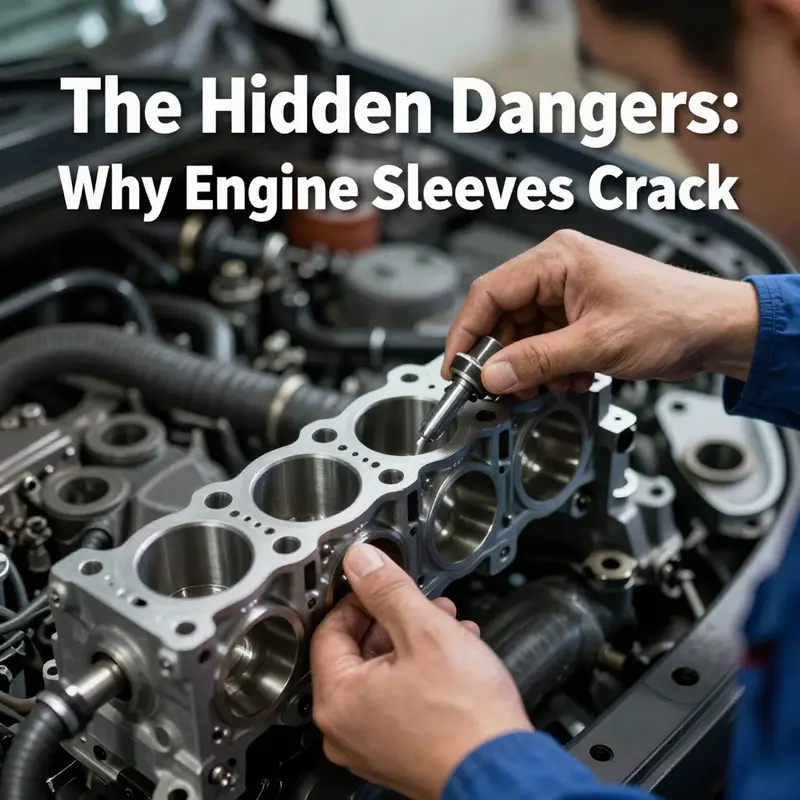
The human factor in assembly cannot be overstated. Clear, consistent torque sequences for cylinder head bolts, accurate alignment of sleeves with bores, and verification of sleeve fit are essential. A misaligned sleeve can create localized bending stresses during firing, which translates into cyclic stresses that fatigue the material. This is why, in the context of engine maintenance, tasks that seem routine—the correct preparation of mating surfaces, the use of proper seating procedures, and adherence to torque specifications—become foundational to fatigue resistance. When fatigue has already set in, these same checks help ensure that a failing sleeve does not experience abrupt, catastrophic fracture under a momentary surge of load. The lessons extend to manufacturing and supply chain practices too: ensuring quality control processes that flag internal voids and porosity, and validating material composition and heat treatment histories, reduces the likelihood that a sleeve leaves the factory with latent defects that could later propagate cracks under normal service.
A comprehensive view of these dynamics begins to reveal why sleeve cracking is so often a symptom of deeper issues elsewhere in the engine’s health. Overheating, for instance, is not merely a symptom of a single failed coolant component. It is often the result of a connectivity of problems: a failed thermostat, a blocked radiator, or degraded coolant that fails to maintain stable heat transfer. Each of these issues raises the thermal stress on the sleeve from every firing event, increasing the conditions that favor PSB formation and crack initiation. Cavitation erosion in wet sleeves adds a mechanical erosion factor that compounds fatigue, especially when the cooling system’s performance is compromised. The cumulative effect is a progressive weakening of the sleeve’s ability to maintain its structural integrity under repetitive loads. In other words, material fatigue does not operate in a vacuum; it thrives on compromised cooling, poor assembly, and the imperfections inherent to manufacturing, all of which can turn a slow, almost imperceptible process into a visible failure over time.
To tie these ideas to practical understanding, consider the path from subtle microcracking to a cracked sleeve. A tiny crack may begin at a grain boundary or near a tool mark that escaped detection during quality control. With each thermal cycle, the crack edges experience field intensification. As stress concentrates at the tip, the crack lengthens incrementally, stealing stiffness from the sleeve and altering the local pressure and temperature distribution around the bore. Piston motion further modulates local loads, and high-frequency vibrations can drive the crack into a growth regime that becomes self-sustaining. Before long, the crack may crack wide enough to alter the sleeve’s bore geometry, producing scuffing, loss of sealing force, and eventually gas leakage into the cooling circuit or oil channels. The engine’s performance then deteriorates—power fades, efficiency drops, and the risk of a more dramatic failure rises. It is a chain of events that underscores the need for vigilance, especially in fleets where engines endure heavy duty, high-temperature operation, and frequent start-stop cycles.
In sum, material fatigue sits at the heart of why engine sleeves crack over time. It is the perpetual marriage of material science and real-world operation, where microscopic defects and grain-boundary physics meet the demanding rhythms of heat, pressure, and motion. The fatigue story explains not only how cracks begin but why they often grow in spite of seemingly modest loads and acceptable operating temperatures. It also clarifies why preventive strategies must be holistic: solid materials engineering, precise manufacturing and assembly, consistent cooling and chemical control, and disciplined maintenance practices. By recognizing fatigue as a fundamental, chronic process rather than a sudden, isolated event, technicians and engineers can better anticipate failure modes and design more resilient sleeves. The chapter you’ve just read is not a forecast of doom but a map of risk factors and levers that, when managed together, can extend sleeve life and keep engines healthier for longer. For readers exploring this further, a broader technical grounding on material fatigue is available at external scholarly resources that describe initiation and growth mechanisms, failure thresholds, and the influence of environmental conditions on fatigue crack propagation.
External resource for further reading: https://www.sciencedirect.com/topics/engineering/material-fatigue
Final thoughts
In conclusion, understanding the reasons behind engine sleeve cracking is crucial for motorcycle and vehicle owners, repair shops, and parts distributors. By acknowledging the effects of thermal stress, improper installation, cavitation erosion, and material fatigue, stakeholders can implement better maintenance practices and improve the overall longevity of engine components. Adopting proactive measures will not only mitigate risks associated with sleeve failure but also enhance the performance and reliability of the engine systems, ultimately leading to cost savings and more satisfied customers.