
Aluminum engines use cylinder sleeves that can be wet or dry, and their removal is a precision task that affects engine reliability, performance, and long-term durability. For motorcycle owners, auto owners, auto parts distributors and wholesalers, and auto repair shops and garages, understanding when and how to strip sleeves is essential. This guide walks you through a safety-first workflow: starting with preparation and safety, moving through identification of sleeve type, executing a controlled dry-liner extraction with the correct pulling tools, and finishing with post-removal inspection, cleaning, and reinstallation considerations. Each section builds on the last to provide a holistic view that helps prevent block damage, leaks, or improper fit. You’ll learn how to select the right tooling, apply penetrating oil correctly, distinguish wet from dry liners, apply gradual, measurable pressure with a puller, and verify bore integrity before reassembly. Whether you work in a well-equipped shop or coordinate with a trusted distributor for the right parts and guidance, the steps outlined here are designed to deliver consistent, reliable results.
Laying the Groundwork: Safe Preparation for Sleeve Extraction in Aluminum Engines
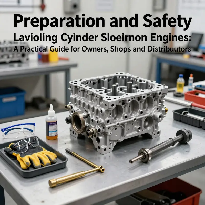
Removing sleeves from an aluminum engine is a precision task that demands discipline before any tool touches metal. The block itself is softer than its iron counterparts, and the delicate nature of aluminum means that haste, missteps, or the wrong choice of technique can turn a straightforward sleeve removal into a costly repair or an engine-block failure. Preparation and safety form the backbone of the entire operation. When done correctly, they protect the engine, the technician, and the surrounding workspace, while also setting up the project for predictable, repeatable results. This chapter focuses on establishing a solid foundation—cooling, electrical safety, fluid management, workspace organization, appropriate tooling, and a clear plan for sleeve type and access. The goal is not merely to remove a part, but to steward a precision process that preserves the integrity of the block and preserves the potential for reliable reassembly if the sleeves are to be replaced or refurbished later.
First, the starting point is the engine itself. Aluminum blocks respond to heat differently than cast iron, and heat cycles can induce distortion or micro-fractures if care is not taken. Begin with a truly cold engine. Surface warmth can mask underlying heat soaking that may occur in the presence of residual coolant or oil, and cold metal is less forgiving of mishandling. A cold engine helps ensure that any brittle or stressed areas remain intact during disassembly. Once you confirm the block is well within ambient temperature, the next fundamental step is to minimize electrical risk. Disconnect the battery, and while the battery’s negative terminal is safest to remove first, ensure all other power feeds and sensors are isolated if you can access them safely. The objective is to eliminate potential shorts or sparks that could occur if coolant or oil residues contact energized circuits during the process. This is particularly important when the engine bay is crowded with components or when the work is performed in a less-than-sterile environment where moisture and conductive debris might mingle with exposed wiring.
Drainage of fluids is the next prudent measure. Coolant and oil contain additives and contaminants that, once spilled, are both a safety concern and a cleanup burden. By draining fluids early and fully, you reduce the risk of pressure build-up, minimize spills, and prevent coolant from spreading into the bearings or into crevices you’ll be working around later. This step also reduces the risk of oil slicks that could cause a slip or an unintended twist of a fragile harness or connector during disassembly. As you drain, the workspace should be prepared to manage residuals—absorbent mats, containment trays, and a plan for disposal in accordance with local regulations. The engine won’t run until reassembled, but a clean, dry surface makes the subsequent steps both safer and more predictable.
Accessories and ancillary systems demand equal attention. The intake and exhaust manifolds, valve covers, timing components, and other peripherals often obscure access to the cylinder sleeves. Before sleeves can be accessed, these components must be removed with care. The approach is not just mechanical but methodical: remove one set of fasteners in a crosswise pattern, gradually, to avoid warping any of the surrounding parts or the block itself. This is particularly important for aluminum blocks where the margins for error are slimmer than in iron blocks. The crosswise loosening pattern helps distribute forces evenly, reducing the chance of bending flanges or cracking housings. It is also wise to document the orientation and sequence of fasteners, especially if you intend to reuse or reuse with new seals. A tidy, organized approach to component removal reduces the cognitive load during the critical sleeve-extraction phase and minimizes the risk of dropped fasteners that could cause damage or get caught in moving parts as you rotate the crank or retract a sleeve.
Securing the engine and the workspace is not a cosmetic concern; it is a safety imperative. An engine that shifts, tilts, or moves during sleeve extraction invites catastrophic consequences. If the engine remains in the vehicle, ensure it’s stabilized with a reliable stand or support system designed for the job. If the engine is out of the vehicle, a properly rated engine stand is essential, and the entire assembly should be bolted and blocked so that it cannot tilt. The surface underneath should be clean and non-slip, with adequate space to maneuver the puller or a drift, a mallet, and the new components that will follow. The environment should be well lit, ventilated, and free from trip hazards. The best practice is to create a dedicated work zone with minimal foot traffic so you can concentrate on aligning tools and applying controlled force without distractions.
With the scene set physically, the selection and handling of tools rise to the forefront. Use only tools that meet manufacturer-specifications or those documented by reputable repair guides. In the sleeve-removal context, dry sleeves in aluminum blocks typically require a dedicated sleeve-puller and the associated support components. A dedicated puller minimizes the risk that you apply leverage in ways that concentrate forces on a single edge or bore, which could nick the bore surface or misalign the block. Penetrating oil befits the preparation phase, not just as an act of loosening a stubborn fit but as a means to reduce friction and corrosion at the interface. A measured application followed by patience is preferable to brute force, especially when the target is not yet seated in a stable, aligned position. The central jack screw should advance smoothly, with the operator watching for resistance rather than tolerating sudden pops or jerks. Aluminum blocks can emit a restrained but noticeable crackle or pop when a sleeve yields; this auditory cue is a guide that the process is progressing, not a signal to increase force. Correct use of a soft mallet, often brass or nylon, around the sleeve top can help relieve binding without imparting impact energy that could fracture edges or deform the bore boundary.
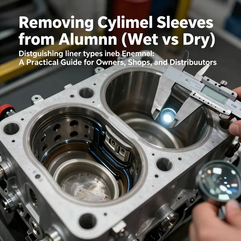
Preliminary sleeve identification is essential, too. Wet liners are cooled by coolant and present a sealing groove, so their removal may be achieved with lighter taps and careful handling. Dry liners, in contrast, are pressed into the block; their removal demands the pulling force distributed through the proper interface of the puller assembly. The distinction matters because the technique dictates not only how you approach the sleeve but how you must protect surrounding features. The plan should be to confirm the sleeve type early in the project to avoid wasting time on the wrong method. If there is any doubt about the sleeve type, cross-reference the engine model’s service manual or the manufacturer’s documentation. These resources often clarify whether the block uses dry sleeves, wet sleeves, or a mixed arrangement and what special precautions accompany each configuration.
A central thread through all of this is the discipline of cleanliness. Aluminum blocks readily show scratches and scoring, and even minor dents on the sleeve rims can become leak-paths or misalignment points upon reassembly. Work surfaces must be clean, and the block’s bore surfaces should be protected during the extraction process. The moment the sleeve shows movement, pause to verify alignment of the puller, the integrity of the edge where the sleeve interacts with the block, and the absence of debris that could fall into the bore or lodge within the block’s coolant passages. If the sleeve resists, stop and reassess. A misapplied force or unbalanced pressure can cause more harm than a slower, patient withdrawal. In some cases, the friction break may be accompanied by a subtle, almost inaudible click as the liner yields; this moment must be interpreted with caution, not as a cue to press harder. The operator’s hands and eyes must stay on the target: a clean, symmetrical withdrawal that preserves the bore and ensures a true interface for the new sleeve.
When preparing to remove sleeves, you must consider what lies beneath. The cylinder bore’s integrity is a foundation of engine reliability. Before any removal begins, examine the bore for surface cracks, corrosion, deep scoring, or any warping that would render the sleeve-removal process risky or even impossible without machining. This forward look is a critical part of safety because it prevents you from chasing a problem you cannot safely repair in-line. If any damage is found, it is far more sensible to consult a machinist or a professional with experience in block resurfacing, sleeve replacement, and bore honing. Attempting to force a damaged bore open or re-sleeve without the necessary precision equipment and measurements can doom the block to future failure. The philosophy is to work with the engine, not against it; if the block looks compromised, the wisest path is to pause, document the anomalies, and seek expertise.
In addition to the mechanical vigilance, ethical and procedural safety also governs this work. Personal protective equipment is non-negotiable. Safety glasses or goggles protect your eyes from mists, oil spray, and metal particles. Gloves shield hands from sharp edges and hot surfaces, and closed-toe shoes guard against dropped components. A well-ventilated space reduces exposure to any solvent or preservative vapors used during the process. It is reasonable to keep a dedicated waste container for oils, solvents, and trace fluids, and to maintain a strict policy of never leaning over or between moving parts when applying puller force. These practices minimize the risk of injury and exposure to harmful substances.
As the sleeve-removal project begins, you also set the stage for subsequent steps. Mark each liner and its corresponding cylinder position before removal, preserving the data needed for reinstallation or for future reference if the block is to be sleeved anew. The marks serve as a memory aid, but they must be durable and resistant to solvent exposure, so a simple, non-erasable coding system works well. It is beneficial, too, to document the technician’s observations: the feel of the liner’s initial resistance, the oil or coolant’s condition at the interface, and any unusual noise or vibration during the process. This narrative notes can be invaluable when planning reassembly, as they expand the knowledge base beyond diagrams and case studies.
The core of preparation is the mindset that precision work is a sequence, not a single act of force. Each step—cooling, disconnecting, draining, removing accessories, securing the engine, choosing the right puller, applying penetrating oil, and executing a controlled extraction—contributes to the final outcome. The risk of attempting DIY without experience is not merely a scratched bore; it is the loss of the engine’s life’s work. If there is any doubt about the job’s feasibility, or if the engine is from a high-performance family where tolerances are tight and the margin for error is small, it is prudent to consult a trained technician or engine specialist who can guide the process or perform the sleeve removal with the right equipment and calibration.
This chapter is not a scanned list of do’s and don’ts but a narrative of preparation that informs every subsequent action. By cultivating a disciplined approach to safety and process, you build a foundation that makes the actual sleeve extraction more predictable and reduces the risk of collateral damage. When the sleeve is finally free, the work will proceed with confidence that the block’s geometry remains true and that any re-sleeving, honing, or machining to follow can be done on a known, solid reference surface. The path to a reliable, reusable aluminum block begins with these quiet, disciplined steps—those that prioritize cooling, cleanliness, correct tool selection, and careful handling over brute force. In the end, the sleeve removal phase is a test of patience, precision, and respect for the material’s delicate nature.
For those who want a deeper dive into the mechanics of sleeve removal and a model procedure that aligns with professional practice, a detailed guide exists that reinforces the strategy described here. It emphasizes alignment, gradual pressure, and the importance of using the correct puller for dry sleeves, as well as the careful handling of sleeves once removed. As you explore those resources, keep the overarching principle in mind: preparation is the cure for uncertainty, and safety is the lingua franca of any serious engine work. The right preparation transforms a potentially risky operation into a controlled sequence that protects both the engine block and the technician’s hands and eyes. If you ever need to review a model procedure or compare the nuances across engine families, turn to the trusted manuals and technical documents that outline the official steps, measurements, and torque specifications that keep an aluminum block’s integrity intact after sleeve removal.
To connect concepts with practical reading, you can explore a dedicated guide that walks through the process of removing engine sleeves and highlights the critical steps for ensuring clean, accurate bore surfaces while maintaining block integrity. how to remove engine sleeves provides a detailed look at tools, alignment, and care during sleeve withdrawal, which complements the safety-first approach outlined here. As you prepare for the actual extraction, reference these procedures to confirm your approach aligns with established standards and to anticipate any engine-specific quirks you might encounter. External resources can offer diagrams, torque specs, and model-specific caveats that further strengthen your preparation plan.
External reference: https://www.motortrend.com/cars/repair-and-maintenance/how-to-replace-cylinder-liners-in-aluminum-engines/
null
null
Dry Cylinder Liner Removal in Aluminum Engines: Precision and Practice
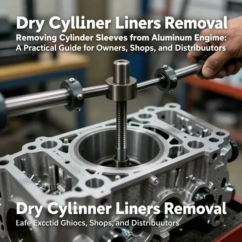
Dry cylinder liners in aluminum engine blocks demand a blend of discipline, the right tools, and a methodical approach. Aluminum warms quickly and can be scored or bent if removal is rushed. A dry liner is pressed into the block and relies on an interference fit to seal and align with the bore. Removing it safely requires controlled axial force, even contact, and attention to bore finish to avoid scoring or warping.
Preparation and planning set the tone for success. Start with a cool engine, disconnect the battery, and isolate fluids. Clean the exterior to minimize debris that could fall into the cylinders. Gather the core tools: a liner puller designed for dry liners, a brass drift or soft mallet, penetrating oil, and appropriate safety gear. Ensure you have a surface that keeps the block supported and accessible to the liner.
Access to the liner begins by removing surrounding components that encase the bore. Detach intake and exhaust components, lift the cylinder head and gasket, and, if required, unseat the crankshaft with careful marking of main bearing caps and positions. Rotate the piston to bottom dead center to maximize clearance and reduce the possibility of piston interference during extraction.
Identifying the sleeve type guides your method. Wet liners are lubricated and may come free with light tapping, but dry liners insist on a purpose-built puller that surrounds the liner evenly. The puller should engage the liner at its outer edge with flush contact points and drive along the axis. Apply penetrating oil to the interfaces and allow dwell time to soften any corrosion.
The extraction sequence is steady and repeatable. Align the puller with the liner, ensure the arms are evenly seated, and square the center bolt with the liner’s axis. Tighten gradually and turn the screw slowly; the liner should begin to yield with a controlled pop as the interference fit releases. If resistance remains, pause, re-oil, recheck alignment, and proceed in small increments.
When the liner exposes itself, lift it away carefully with the puller attached. Avoid twisting or bending the liner edge, and monitor for any scoring of the bore. After removal, inspect the bore with care for scoring, corrosion, or signs of heat damage. Measure bore diameter with appropriate gauges and compare to service specifications. If the bore remains within tolerance, prepare for the installation of a new liner with clean surfaces and correct seal geometry. If the bore is out of spec, plan for block rework or replacement.
An alternative removal method exists but is a last resort. Without the proper puller, some technicians rock the liner by gently tapping the top edge with a brass drift while applying upward pressure at the base. This approach risks gouging the bore or distorting the block and should only be used when proper tooling is unavailable and with extreme caution.
Documentation completes the process. Mark every liner with its original position, never mix liners between cylinders, and log the measured bore condition and the seating surface state. New seals or gaskets are installed per the manufacturer guidance, and reassembly proceeds with attention to torque, alignment, and cleanliness. In the end, the objective is to restore the block to service with predictable tolerances and reliable sealing surfaces, ready for inspection, machining if required, and reassembly.
Post-Removal Vigilance: Inspecting, Cleaning, and Reinstalling Cylinder Sleeves in Aluminum Engines
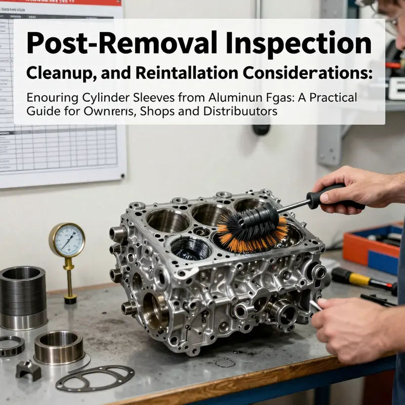
When the sleeves are finally coaxed free from an aluminum engine block, the process does not end with a simple wipe and a bolt-on rebuild. The phase that follows is where precision matters most. The bore has just endured a sequence of thermal swings, mechanical pressures, and potential micro-movements during extraction. The goal now is to determine whether the block remains sound enough to accept new sleeves and, if so, to restore a pristine seating surface that will seal and hold under load for the life of the engine. The assessment begins with a clear, methodical inspection of what the block shows and what the sleeve reveals once it is out of the bore. A careful eye will look for scoring, micro-cracks, corrosion, or any deformation that hints at past over-temperature events or misalignment, all of which can compromise the reinstallation. If the bore or deck looks damaged beyond acceptable limits, the repair path changes from reuse to reconditioning, which might mean honed or bored re-sleeving, or even block replacement in severe cases. In practical terms, the inspection is a discipline of noting, measuring, and confirming that every surface that touches the new sleeve is within the manufacturer’s tolerances and free of debris that could disrupt a proper seal. A typical soft rule of thumb is to treat the bore as a living surface until proven otherwise; the absence of obvious flaws does not guarantee a perfect seat, so verification steps are essential. A thorough visual sweep should be paired with precise measurements using tools calibrated to the engine’s spec. A bore gauge, for instance, provides a dimensional picture that transcendental scanning cannot convey. The first check is roundness and diameter variation along the length of the bore. Any deviation from the accepted diameter—whether a taper, out-of-round condition, or a localized wear mark—must be reconciled before attempting to reinsert a sleeve. Even minor deviations can create edge loading on the new sleeve, inviting leaks or accelerated wear. The saw-tooth texture of wear marks can betray an overheating history or a misalignment during previous assembly. If such signatures appear, the technician evaluates whether a light honing or a more aggressive bore restoration is warranted, always in line with the engine’s service manual. The sleeves themselves deserve equal scrutiny. As the tools slide the sleeve from the block, the interior surface of the sleeve may reveal ridges, pitting, or contact marks that tell a story about lubrication, coolant exposure, and piston travel. In some cases, wear patterns indicate that the sleeve has carried uneven loads, a symptom of prior core shifts or nonuniform combustion events. When the sleeve shows consistent wear bands and an intact sealing surface, it becomes a reference point for what an ideal new sleeve should emulate, but it is not a substitute for the block’s cleanliness. Cleaning the bore and preparing the ring lands become the next critical steps. The cleaning process must remove all residual oils, metal particles, or old gasket remnants without introducing new scratches. A non-abrasive cleaner, followed by a careful wipe with lint-free cloths, minimizes the risk of contaminant introduction. Isopropyl alcohol is often a practical choice for final wipe-downs, as it evaporates quickly and leaves little residue. The objective is to present surfaces that are visually and electronically clean, free of debris that could lodge in the sealing grooves or bore irregularities. A light, evenly applied solvent bath can also help lift fine particles that a hurried wipe may miss, but the cleaning must be followed by meticulous drying with compressed air and careful hand inspection. After cleaning, a practical test of surface integrity is warranted. A straightedge across the bore can reveal subtle warping or deck misalignment that might not be obvious at first glance. If the straightedge reveals gaps, the block’s deck surface may require resurfacing to restore a true seating plane before reinstallation. A block that cannot be resurfaced to meet spec becomes a candidate for more extensive repair or, in some cases, replacement. This sequence—visual inspection, dimensional verification, and surface conditioning—lays the groundwork for the reinstallation phase. It is here that the decision to reuse the original block or to step into a re-sleeving or a complete block refurbishment is crystallized, and the line between viability and failure becomes sharply defined. As a practical reference, those who want to refresh their memory on the removal sequence can consult a focused guide such as How to remove engine sleeves. The link provides a concise, illustrated reminder of the critical orientation and handling steps that precede what comes next in the rebuild. Returning to the current stage, the reinstallation considerations demand equally careful preparation. There is a rhythm to this work, a rhythm that respects both the material properties of aluminum and the engineering demands of a reliable seal. The outer surface of a new sleeve, when prepared for insertion, receives a light coating of clean engine oil or a suitable dry lubricant, ensuring the sleeve slides into place without galling. The block bore must be impeccably clean and dry; any moisture or contaminants can interrupt the interference fit and create an unwanted gap or micro-movement that invites oil leaks or combustion gas ingestion. The sleeve material and finish must be matched to the engine’s service load and operating temperature. Dry sleeves, which are common in modern aluminum blocks, require particular respect for the interference fit; wet sleeves may allow a slightly different installation approach, since coolant boundaries interact differently with the bore. In either case, the alignment of the sleeve in the bore is everything. A misaligned sleeve is not just a minor inconvenience; it is a potential failure point under compression, heat, and cyclic loading. Modern practice favors a controlled press fit or a carefully guided heating-and-cooling method that expands the bore or contracts the sleeve just enough to seat it evenly. The installation must be performed with a purpose-built sleeve installer or a hydraulic press that applies uniform pressure along the circumference. The risk of hammer blows, taps with punches, or sharp prying is high, because sudden shocks can crack the aluminum or create micro-imperfections that later propagate into leaks. The edges where the sleeve meets the deck should align flush with the top surface, and the sleeve should sit squarely within the bore with no tilt. After seating, a thorough post-installation check confirms the seating depth and the alignment of the sleeve with respect to the block deck. There is a moment of stillness after the sleeve is in place, followed by careful measurement to verify that the bore diameter remains within tolerance with the new sleeve installed. The next stage is to ensure the sealing surfaces and coolant boundaries are correctly established. If a dry sleeve uses a sealing region at the top or bottom, any distortion here would defeat the purpose of the seal and lead to leakage or cooling inefficiency. The sealing interface must be clean and free of nicks, scratches, or burrs that could compromise the seal. A light lapping or careful refinishing of the sealing faces may be necessary if the surface shows any irregularity. Reassembly then proceeds with the cylinder head, gaskets, and the rest of the engine’s upper assembly, observing the torque sequence and tightening values specified by the manufacturer. The torque values and patterns are not arbitrary; they are the culmination of the block’s geometry, the sleeve’s interference fit, and the head gasket’s properties. A misstep here can alter the block’s planar geometry or warp the deck, producing a new set of sealing problems. When the assembly reaches a torquing stage, attention to sequence is essential. In most engines, the head bolts must be tightened in a specific cross-cross order to distribute load evenly and to maintain a consistent gasket seal around every cylinder. Following the spec, even the final stage of tightening is a moment of quiet precision that determines the engine’s ability to withstand thermal cycles without leaking. Once the upper assemblies are reinstalled, the engine would typically be partially tested to verify that no abnormal clearance or binding exists. A careful rotation of the crank through several cycles ensures that the pistons travel freely and that no binding occurs at the ring lands or within the bore. If any drag is detected, a re-check of sleeve seating, bore cleanliness, and deck flatness is warranted before continuing with the full engine rebuild. The process is patient and measured because aluminum blocks, though light and efficient, demand respect for their sensitivity to machining tolerances and thermal expansion. The importance of cleanliness cannot be overstated; contamination is the silent killer of a fresh sleeve’s life, and even microscopic particles can create rapid wear that shortens the operational life of the entire engine. The flow of coolant must be verified for leaks once the head is secured, and the compression components must be checked for any misalignment that could disrupt air or fuel delivery. In the event of a need for further guidance on sleeve installation specifics, reference to manufacturer documentation or professional repair manuals is prudent, as these resources codify the exacting tolerances and steps unique to each engine family. For ongoing accuracy, the reinstallation sequence should be accompanied by careful documentation: marking the sleeve positions, noting any deviations found during inspection, and recording the measurements obtained after installation. This historical record facilitates future maintenance and ensures the assembly can be serviced with confidence should a later overhaul be required. Finally, as the engine nears commissioning, the importance of seal integrity and coolant containment remains paramount. Replacing gaskets with new versions designed for the engine and ensuring sealing surfaces remain pristine protects the investment in the sleeve and the block. The entire procedure—the removal, inspection, cleaning, re-sleeving, reassembly, and verification—balances the art of mechanical intuition with the discipline of precise measurement. It is a reminder that even a seemingly straightforward task like sleeve removal is the gateway to a successful engine rebuild when performed with patience, accuracy, and adherence to documented specifications. For readers seeking a broader context of the sleeves’ role throughout the engine’s life, external reference materials provide a technical backdrop that complements hands-on practice, including reliable manuals that document the intricacies of sleeve geometry, material choices, and the best methods for achieving reliable fits in aluminum blocks. External resource: https://www.helminc.com
Final thoughts
Stripping sleeves from aluminum engines is a precise operation that hinges on safe preparation, correct sleeve identification, and controlled, tool-appropriate removal. By starting with a clean workspace and the right penetrating oil and puller, you minimize the risk of scuffing or warping the block. Distinguishing wet from dry liners is essential to selecting the appropriate removal method and avoiding costly damage. When removing a dry liner, apply gradual, even pressure and verify movement before continuing. After extraction, thorough bore cleaning, damage inspection, and careful reinstallation with new seals and manufacturer torque specs ensure the engine once again delivers reliable performance. Whether you’re a shop owner, distributor, or DIY enthusiast, adhering to these steps will help you complete sleeve stripping with confidence and repeatable results.