Cylinder sleeves (liners) in diesel engines are precision components that influence bore integrity, sealing, and longevity. Removing them is a task that sits at the crossroads of machining, engine assembly, and rigorous workshop safety. Whether you’re a motorcycle owner pursuing a diesel build, a car owner maintaining a heavy-duty engine, a parts distributor stocking sleeve products, or a repair shop handling sleeve replacement for customers, understanding the full lifecycle—from preparation to extraction and references for model-specific procedures—reduces risk, protects the block, and speeds up turnaround. The five-chapter structure below ties together core concepts: how to prepare the engine and workspace with safety as a baseline, how to approach disassembly of the cylinder head and related components that might block access, how to select and apply specialized sleeve-removal tooling, how to execute a controlled lifting and extraction of sleeves without damaging the bore, and how to navigate model-specific manuals and references to ensure correct reassembly and future reliability. Put simply, effective sleeve removal begins with clean, organized preparation; proceeds through measured disassembly and tool use; relies on careful handling during extraction; and ends with verification against manufacturer specifications. For owners and technicians, this integrated view clarifies tooling needs, inspection points (seal rings, bore finish, sleeve seating), and the critical role of service manuals in every model. The steps are applicable across diesel engines used in motorcycles, cars, and light-to-midweight applications, and they align with professional practice: respect for the bore and sleeve interface, strict cleanliness, proper alignment, and documented torque and seating references. As you read, you’ll see how each phase builds on the previous one, reinforcing safety, precision, and readiness for a proper reinstallation or rebuild when sleeves are due for replacement.
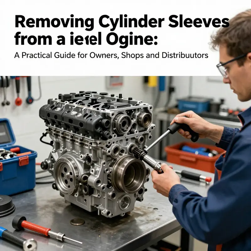
Laying the Groundwork for Sleeve Removal: Preparation, Safety, and the Quiet Precision of a Diesel Engine Rebuild
Laying the groundwork for removing sleeves from a diesel engine is more than a sequence of steps. It is a disciplined mindset that treats the engine block as a precise, multi-material ecosystem. When the goal is to pull sleeves without disturbing the bore geometry, every move must be deliberate, measured, and repeatable. This chapter threads preparation and safety into a fluid narrative, showing how the right conditions, tools, and habits transform a potential gamble into a controlled operation. The work begins long before any wrench touches metal. It starts with knowing that sleeves sit as a pressure-locked interface between the liquid-cooled world inside the block and the moving combustion world that lives in the bore. The task demands respect for heat, chemistry, and mechanical fit. With that respect, the technician sets the stage for success by aligning the environment with the job in hand, not by improvising when the risk is highest.
Cooling and de-energizing the system anchors the entire process. Engine components contract and expand with temperature shifts; a hot engine is a recipe for warping, misalignment, and injury. The first action is to ensure the engine is completely cool to the touch and disconnected from any power source. Then comes a careful sequence of fluid management. Draining oil and coolant is not merely a convenience; it prevents contamination, reduces the chance of accidental spills, and protects the bore and surrounding webs from fluid carryover during disassembly. The container plan matters too: used oil and coolant demand environmentally responsible disposal. A clean, controlled workspace keeps particulates from invading the crankcase and oil galleries, preserving cleanliness for the next steps and for post-removal inspection.
Once fluids are in containers, the outer barrier around the block comes into focus. Removing external components is not a cosmetic chore but a strategic one. The radiator, intake system, exhaust manifold, turbo piping, wiring harnesses, and various covers must be detached with care. Labeling every part and fastener becomes a quiet ritual that pays off during reassembly. The goal is not to create a neat pile of parts but to map a reliable restoration path. Each bracket, hose, and sensor has a home in the rebuild. A mislaid part can derail timing, fuel delivery, and cooling—the sort of disruption the sleeve-removal process cannot tolerate. In this phase, protection for the block also matters. The crankcase and exposed passages should be shielded with clean cloths or plastic sheeting to prevent debris from dropping into the oil pan or into sensitive cores. A clean workspace is, in effect, a guarantee that the work will stay within tolerances rather than wander into mishap.
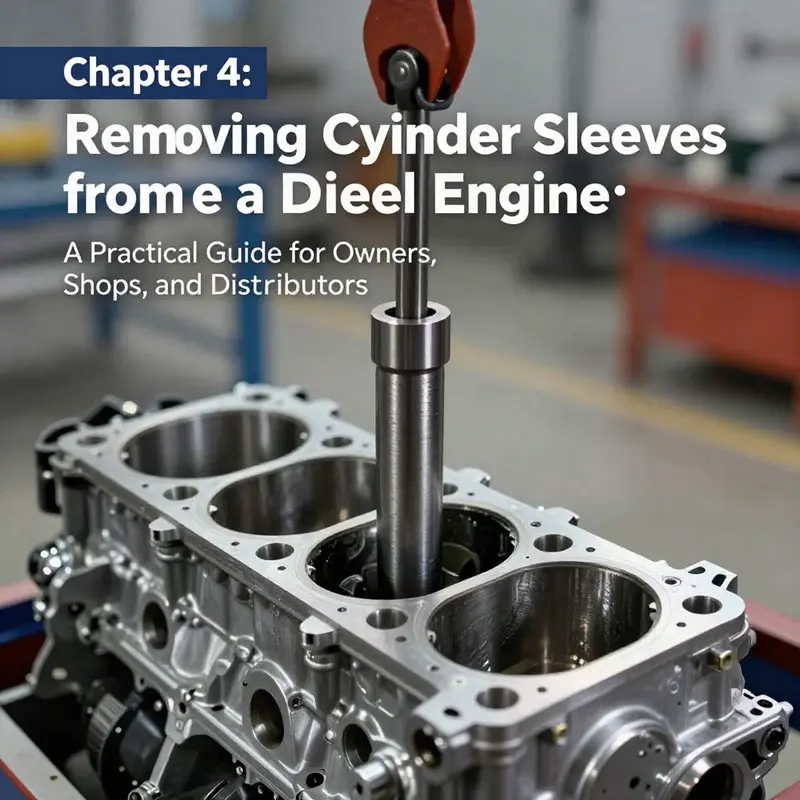
The heart of preparation centers on the readiness of the right tools and the proper approach to sleeve removal itself. Sleeves are press-fit into the block and require a deliberate, well-fixtured puller system to coax them free without scars to the bore or to the sleeve seat. The preparation phase, then, must include selecting a sleeve-puller arrangement that matches the engine’s geometry and the sleeve’s material. Mechanical, hydraulic, or pneumatic pullers each have a place, depending on bore size, sleeve thickness, and the force profile needed to advance the sleeve without tilting or binding. A pad plate on the block surface helps distribute the load across the cylinder head region, while a base plate lines up with the lower portion of the sleeve. The puller rod travels through the bore’s center, guided by the alignment of the plates, and the nut is tightened gradually. The aim is a steady, even lift that disrupts the seal only at the intended moment when the sealing ring clears the bore and the sleeve becomes free. Throughout this stage, the technician must monitor centering and smoothness of motion, because any lateral drift can nick the bore or distort the sleeve’s path. As a reminder of the path forward, the guidance from established manuals emphasizes exact alignment, torque values, and coordinated movement rather than forceful, uncontrolled pulling.
To navigate these subtleties, the preparation phase also integrates a thorough safety culture. Personal protective equipment is non-negotiable: safety glasses to guard against flying debris, heavy-duty gloves to protect hands from sharp edges and hot surfaces, and steel-toed boots to handle heavy blocks and tools. The work area should be bright, clean, and organized, with tools off the floor to avoid trips and with parts cataloged so reassembly can be done confidently. A routine inspection of pulling equipment is essential. Worn, cracked, or deformed mounting hardware can catastrophically fail under load, turning a controlled procedure into a dangerous event. The rule of thumb is simple: never apply force with a tool that has any sign of wear. Additionally, the application of force must be measured and deliberate. Sudden jerks or overtightening create stress concentrations that can fracture the block, crack a sleeve seat, or misalign the piston axis. When heavy components such as a block or cylinder head are moved, proper lifting techniques and mechanical aids protect the technician from back injuries and from dropping expensive parts.
The narrative of preparation also embraces procedural discipline. Before any pulling begins, the source material highlights the necessity of foreknowledge: consult the engine’s service manual for the exact tool configuration, the sequence, and the required tolerances. The unique geometry of each engine model means that the best practice is not a one-size-fits-all recipe but a model-specific protocol. This is where the value of manufacturer guidance becomes clear. For model-specific instructions on alignment, torque values, and safe handling, technicians routinely turn to official technical resources that document the intended method and the permissible variance. In this context, a knowledgeable reference can bridge the gap between generic technique and the tailored requirements of a particular engine family.
As you progress through preparation, the importance of documented procedures becomes a thread that anchors the entire operation. The mental map you build during these early steps reduces the risk of missteps when the time comes to engage the sleeve-puller. If the model you are working on has particular seating or sealing features, the service manual will spell out which seals should remain intact or require replacement and what specialized alignment aids exist to ensure the sleeve’s seating surface remains true. Integrating this model-aware mindset with the physical steps that follow—such as setting up the puller, centering the assembly, and applying a controlled extraction force—transforms sleeve removal from brute force into a craft that respects both engineer intent and material realities. For practitioners seeking to broaden their understanding of the process, the topic of engine sleeves and their function is richly explained in dedicated resources that explore material selection, sleeve types, and their implications for cooling and lubrication. See how-to resources on removing engine sleeves for a practical, hands-on perspective on the procedure and its nuances, including the central role of alignment and controlled force in preventing bore damage. how to remove engine sleeves
With preparation complete, the driver behind the sleeve removal becomes a clear, methodical sequence rather than a guess. The discipline of cooling, draining, disassembly, alignment, and controlled pulling creates a chain of safeguard steps that reduces risk to the engine block and to the technician. This foundation also supports the subsequent phases of the operation, where the exacting requirements for sleeve extraction—centered load, even force distribution, and meticulous handling of the sleeve along its axis—are executed with confidence rather than improvisation. In the end, the success of sleeve removal hinges on not breaking the first rule: prepare the environment, prepare the tools, and prepare the mind to follow the procedure with patience. The rest follows in a predictable, controlled fashion when preparation is given its due.
External reference for deeper, model-specific guidance and torque specifications can be found in official service manuals and technical service documents. For a detailed, authoritative treatment of cylinder liner replacement and related procedures, consult the manufacturer’s technical service resources, which provide step-by-step procedures, alignment guidance, and safety precautions tailored to industrial and heavy-duty diesel engines. External resource: https://www.cummins.com/support/technical-service-manuals
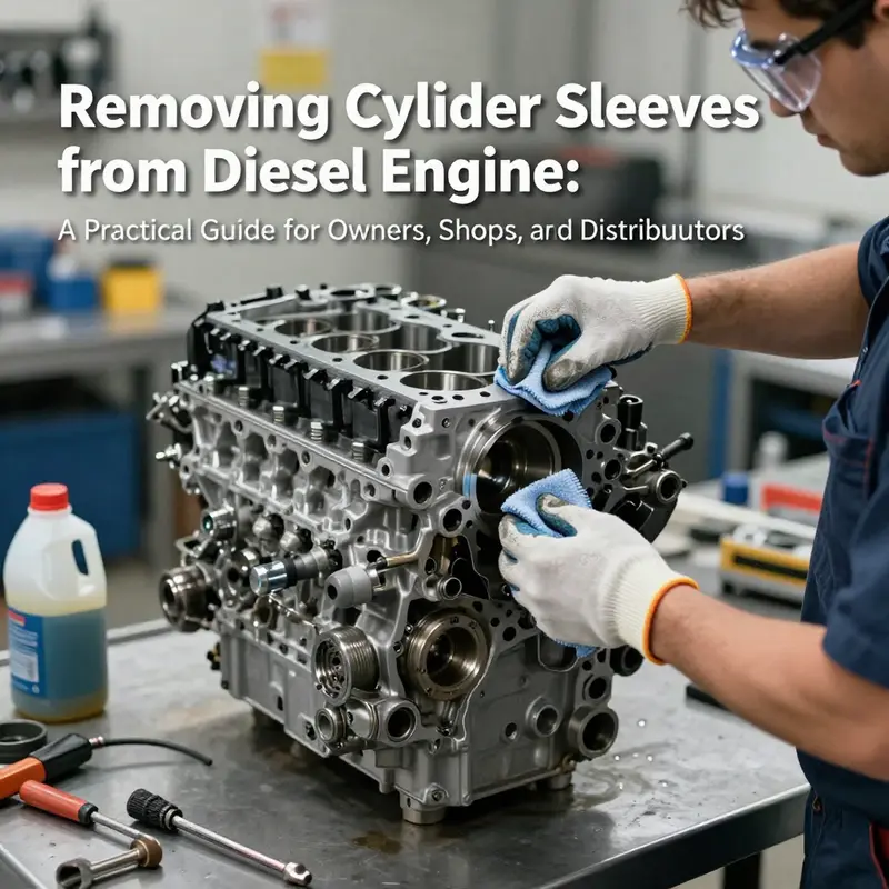
Disassembly as Access: Precision Cylinder-Head Work as the Gateway to Safe Diesel Sleeve Removal
Disassembly of a diesel engine to remove sleeves is not merely a matter of loosening a few fasteners; it is a deliberate preparation of access. The cylinder head sits atop the engine block like a lid on a complex mechanism, sealing the combustion chamber, bearing high pressures, and providing the interface for fuel delivery, cooling, and exhaust. Before the sleeve can be reached, the technician must prepare the workspace, protect the block, and execute a sequence that preserves the integrity of every part involved. The process begins with a careful assessment of the engine’s current state. If the engine has been overheating, if there is coolant or oil contamination near the head gasket area, or if there are signs of corrosion around the liner seating surfaces, those conditions must be addressed and documented before any disassembly proceeds. Proper preparation reduces the risk of warping, gasket damage, or misalignment during reassembly, and it also minimizes the chance of foreign debris entering the crankcase or the oil passages during the operation. Safety, cleanliness, and organization form the quiet backbone of a successful sleeve extraction.
Cool down and power isolation are the first operational imperatives. The engine should be completely cool to prevent thermal shock to metal components and to reduce the risk of residual pressure in the cooling system. Disconnecting the battery and isolating the electrical harnesses eliminates the chance of accidental cranking while components are being loosened and moved. Draining the cooling system and the oil ensures that the head area is not pressurized by fluid and that a clean, dry surface is available for inspection. With fluids out of the way, the technician can begin the more visible steps: removing the external components that shield the head from view and access. Radiators, intake and exhaust manifolds, fuel lines, and any wiring or sensors connected to the head must be detached in a controlled and labeled manner. Working in a methodical sequence reduces the risk of misplacing parts when it is time for reassembly.
The next phase involves laying a protective layer over the crankcase and any exposed surfaces. Clean cloths or plastic sheeting are placed to prevent debris from falling into oil passages, oil galleries, and bearing caps. A clean working surface becomes a reference point for alignment checks later in the procedure. Removal of the cylinder head itself requires adherence to the manufacturer’s torque sequence. In most engines, the head bolts are loosened in a crisscross pattern, beginning with bolts on the outer edges and moving toward the center. This approach minimizes the risk of warping or bending the head plate. The bolts are loosened gradually in several passes, keeping tension even and predictable. When the head is finally released, it is lifted straight up and away from the block to avoid scoring the gasket surface or nicking the mating faces. Once the head is on a clean surface, the gasket surface is inspected thoroughly for signs of damage, warping, or residue that could compromise the seal on reinstall.
Attention then shifts to the sealing elements around the liner. Cylinder sleeves are typically sealed with an O-ring or a gasket at the interface with the block. These seals may degrade over time, creating slow leaks that can contaminate cooling passages or combustion products. A careful inspection of the seating area around each liner helps determine whether the sleeve can be removed without damage, or if more aggressive support is needed to prevent scattering of debris into the bore. With the head removed, the area around the sleeves is cleaned and dried so that any later marks or engraving indicating sleeve orientation can be seen clearly. Some technicians prefer to mark the liner position before extraction; others rely on OEM reference points that appear on the bore wall or the seating face. Either approach aims to preserve orientation during reinstall and to ensure the bore remains perfectly coaxial after the sleeve comes out.
Having prepared the workspace and performed initial inspection, the technician turns to the specialized tools required for sleeve removal. The sleeve is press-fit into the block, and extracting it without damage demands a tool that can apply even, controlled force. Hydraulic sleeve pullers are common for large industrial and heavy-duty diesel engines. They distribute force uniformly and can extract a stubborn liner with less risk of tapering or scoring the bore. Mechanical pullers, while simpler and less expensive, apply force through a screw mechanism and can be effective for smaller engines or when space is constrained. The choice between hydraulic and mechanical pullers is dictated by the engine’s size, the liner material, and the access available in the cylinder bore.
A robust sleeve puller setup typically includes a top support plate that rests on the upper surface of the block, a central pulling rod that runs through the bore, and a lower support or jack plate positioned beneath the liner. The puller nut is threaded onto the rod above the top plate, and the technician tightens gradually. The key is to maintain the puller’s alignment with the liner axis so that the force is evenly applied around the liner’s circumference. Misalignment can create bending forces that crack the bore or distort the liner seating surface. In practice, as the sleeve begins to break free, it is essential to maintain steady, incremental torque on the puller to avoid abrupt movements that could damage the block. As the seal clears the bore, the sleeve can be drawn upward, and a crane or hoist can then assist in lifting the liner out of the block. The removed sleeve should be handled with care, placed on a clean surface, and kept aligned with its cylinder axis to avoid deformation of the delicate sealing surfaces.
This is where the narrative of disassembly links to the broader rebuilding effort. After removal, every bore experiences a moment of truth: is there scoring, pitting, or out-of-round wear that would affect the fit of a new liner? A precise bore measurement using a bore gauge yields data that guides whether the block can be reused as-is, needs honing, or requires boring to restore proper tolerances. The liner seating surface within the block must be clean, free of corrosion, and flat enough to guarantee a proper seal with the replacement sleeve. The replacement sleeve is typically installed using a press-fit or a thermal expansion method, depending on whether it is a dry sleeve or a wet sleeve with an O-ring seal. The outer surface of the new liner is lubricated with clean engine oil or a specialty sleeve lubricant to ease installation, and its depth is verified with a depth gauge. Alignment during seating is critical; any misalignment can create a gap that invites leakage or insufficient sealing. In programs that rely on OEM designs, the seating is often validated with a dial indicator to confirm seating depth as well as concentricity with the bore.
The reassembly sequence then circles back to the cylinder head and the rest of the valvetrain. A new head gasket is installed, and the head is torqued to specification in the correct sequence. It is crucial to reinstall the timing components, fuel lines, oil and coolant circuits, and all sensors with accurate connections and secure fastenings. After the head is torqued, the typical path includes reinstalling the intake and exhaust manifolds, then the associated plumbing and electrical harnesses. Once the engine is buttoned back up, the system is refilled with fresh oil and coolant, and the engine is prepared for a leak-down test and a compression check. These tests confirm the sealing integrity of the repaired block and the proper seating of the sleeves before the engine is started for the first time after service.
In practice, technicians continually emphasize adherence to the manufacturer’s service manual for torque values, sequencing, and tooling requirements because designs vary significantly between engine models. The disassembly of the cylinder head and related components is a foundational, high-value step that determines whether sleeve replacement can proceed smoothly and whether the rebuilt engine will meet its reliability targets. For those seeking hands-on reference and model-specific nuances, a practical field resource shows how sleeve tooling and process steps interlock in real-world work: How to remove engine sleeves.
Finally, engineers and shop practitioners alike acknowledge that the integrity of the sleeve-removal process hinges on meticulous preparation, careful handling of the head and seals, and disciplined reassembly. The path from disassembly to reliable operation passes through clean surfaces, precise alignment, and a disciplined approach to inspecting bore condition and seating geometry. When done correctly, this sequence preserves the block’s structural integrity, ensures proper sealing of the new liner, and sets the stage for a durable rebuild. For researchers and technicians seeking a detailed, model-specific procedure, official service manuals and OEM guides remain the gold standard reference. External resources can supplement this knowledge, providing deeper procedural specifics and diagnostic checks that underpin successful sleeve replacement in modern diesel engines.
External resource: https://www.bosch-diesel.com/service-manuals/diesel-engine-cylinder-liner-removal-guide
null
null
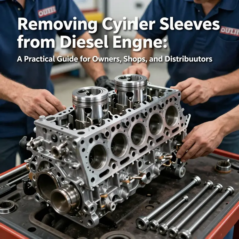
Lifting the Liners: A Precision-Driven Roadmap for Removing Diesel Engine Sleeves
Removing cylinder sleeves from a diesel engine is not a routine bolt-and-go task. It sits at the intersection of precision machining, careful alignment, and meticulous protection of the block itself. When sleeves are inspected, bored, or eventually replaced, the process demands a calm, methodical approach. The operation hinges on three things: the right tooling, a clean, well-supported work environment, and a disciplined sequence that preserves bore geometry and block integrity. This chapter follows that logic, weaving together the preparation, the specialized techniques, and the checks that keep the engine block from becoming the casualty of a difficult extraction. If you’ve read through the background on why sleeves fail or how they’re seated in the block, you’ll recognize the lifting phase as the climactic moment where misalignment or uneven force can translate into costly damage. A focused, model-agnostic mindset helps; the specifics may change, but the core principles remain constant.
Preparation begins long before the sleeve comes under load. First, the engine must be cool, completely de-energized, and immobilized. Heat and pressure are enemies here, not allies. With the engine secured, the next step is to remove the obstructing components so access to the bore is clean and direct. Radiator, intake, exhaust, and any covers that shield the block must yield to careful disassembly. The goal is to leave a pristine work arena around each cylinder so that the lip, flange, and the surrounding boss are visible and unscarred. Even a tiny particle of grit can become a lever that chips a bore wall under load. Protective coverings for the crankcase and oil pan are essential; a clean cloth or plastic sheet acts as a shield against dust and metal shavings that could otherwise find their way into oil channels or oil-coated surfaces.
Disassembly follows with purpose. Removing the cylinder head is an operation in its own right, requiring attention to the head gasket and the sequence of torque reversals specified by the manufacturer. Once the head is off, the gasket is inspected for signs of heat damage or warping; this helps determine whether further teardown is needed or if the sleeve extraction can proceed without compromising the head sealing surface. In some cases, it isn’t necessary to pull pistons or disconnect rod assemblies if you only need to extract a sleeve and that sleeve can be freed without disturbing the piston assembly. The alignment of the bore, the sleeve’s sealing ring, and the boss geometry around the bore all become critical once the sleeve begins to move. This is not the moment to improvise; it’s the moment to observe, confirm, and prepare.
A dedicated sleeve puller system is the engine’s ally here. Sleeves are pressed into the block and require a controlled, centered pull to release them without galling the bore or distorting the block face. Mechanical pullers offer precise, incremental force and are well-suited for regular service and moderate engines. Hydraulic pullers bring substantial force with less manual effort, which is helpful when sleeves are tightly bonded or corroded. Pneumatic pullers speed up cycles in high-volume environments but demand strong control to prevent misalignment. When choosing tooling, several criteria guide the decision: compatibility with the bore diameter and sleeve geometry, adjustable arms to adapt to different sleeves, robust construction to withstand the loads, and alignment features that ensure the pulling force remains perpendicular to the bore. The goal is to create even contact at flange or boss contact surfaces, eliminating any tilt that could bind the sleeve or scar the block walls.
The setup around the engine is as important as the puller itself. You’ll need adapters, jaws, or cleats matched to the sleeve’s exterior geometry so the contact is firm and even. A readied fixture stabilizes the block and keeps the bearing surfaces from bending under load. A light coating of penetrating oil around a seized sleeve often helps, but the oil must not sneak into the bore during extraction. Backup rigs can protect the block if the sleeve binds or if unexpected resistance appears. Pre-operation checks set the stage: clean the bore area, inspect for cracks or distortions in the cylinder boss, and ensure there are no burrs on the seating surface that could bite into the sleeve during pull.
The actual extraction hinges on careful, measured action. Align the puller with the bore, engage the correct flange contact points, and begin with light, even pressure. The puller’s force should be applied gradually, with continuous checks on alignment. If the sleeve begins to tilt or bind, stop and re-seat the puller, verify contact surfaces, and re-apply with a measured increment. A common challenge is a sleeve that resists initial movement due to a tight sealing ring or a slight bonding with the bore. In such cases, more penetrating oil and dwell time often yield results, paired with a gentle heat application to the surrounding block area to expand the bore ever so slightly. It’s critical to avoid rapid, jerky motions or excessive torque, as these can bend or crack the block, especially near the shoulder of the bore or where the bore meets the deck surface.
Once the sleeve breaks free from the block and the sealing ring clears the bore, the extraction can continue with steadier, controlled force until the sleeve is fully atop the puller and begins to disengage from the bore. A crane or hoist is then used to lift the sleeve clear, maintaining alignment with the cylinder axis to prevent side loads that could damage bore walls. The sleeve should be placed on a clean, protected surface to avoid nicks or deformation before any measurement or inspection. This moment—seeing the sleeve come free—often reveals the first hints of deeper issues: micro-cracking around the bore, uneven wear along the sleeve seating surface, or residual corrosion at the base of the bore. Each clue informs the next steps in replacement or further machining.
Post-extraction inspection becomes a diagnostic bridge to the subsequent phase. The bore is checked for chatter marks, scoring, or out-of-round conditions, and measurements are taken to verify roundness and diameter. Deburring is performed with care, and the seating face is cleaned to remove oil films, carbonized residues, and fabrication debris. If a new sleeve is to be installed, bore preparation focuses on achieving a true, perpendicular seating surface with clean oil-free conditions that promote even seating. The replacement sleeve must match the original bore’s diameter and depth to ensure a proper seal and predictable heat transfer. The installation method—whether a press fit, interference fit, or a light lubrication protocol—follows OEM guidance and tolerances. Refastening torque on related components is checked after reassembly to confirm alignment and a stable deck plane.
The process documentation that follows is frequently undervalued yet essential. Recording the tools used, the exact sequence followed, any anomalies encountered, and the measurements taken—bore diameter, roundness, sleeve seating depth—creates a trail that can guide future service and help troubleshoot if leakage or misalignment occurs after reassembly. OEM manuals and service literature are the definitive sources for tolerances and lubricant requirements; if the model has unique features or nonstandard geometries, model-specific guidance becomes indispensable. For practitioners seeking a model-anchored walkthrough, there is value in consulting step-by-step resources that illustrate the exact contact points and alignment checks for a given bore configuration. In practice, that means balancing universal principles with the specifics your engine model demands. To deepen practical understanding, you can refer to a detailed model-focused guide that lays out the sleeve removal steps in a structured format, such as a dedicated article that mirrors the approach described here: how-to-remove-engine-sleeves.
In closing, lifting and extracting sleeves is a high-precision operation where preparation, tooling, alignment, and controlled force converge to protect the engine block and enable reliable sleeved-bore reconditioning. The highest yield comes from treating the sleeve as a precision component rather than a stubborn obstacle. The better you prepare, the more predictable the outcome, and the less time the engine spends out of service. For those seeking broader technical grounding or model-specific nuance, OEM service literature remains the gold standard as you plan your next steps, including the selection of compatible sleeves and the verification of fit after installation. External reference: https://www.cummins.com/support/technical-service-manuals.
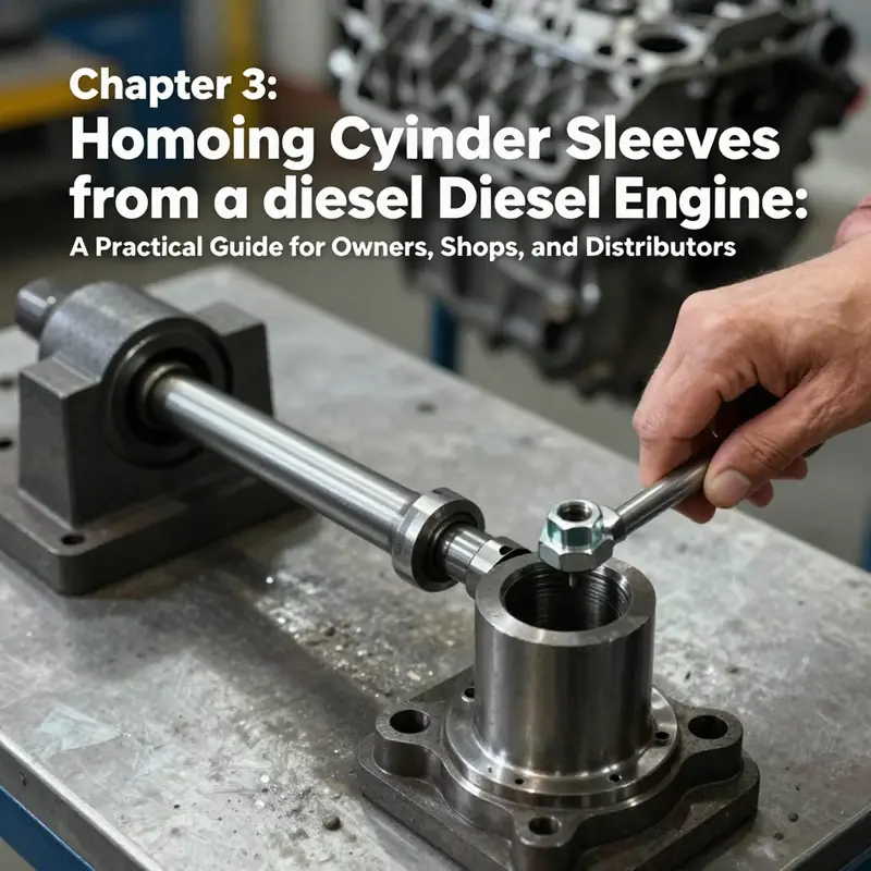
Model-Driven Precision: Navigating Sleeve Removal in Diesel Engines with Manuals and Tools
Removing cylinder sleeves from a diesel engine is a precision task that demands more than brute force. It hinges on model-specific realities that influence every choice from the puller you deploy to the holding force you apply. The sleeve design—whether dry or wet, whether integrated with an O-ring seal or a gasket, and how it sits in the block—determines the safest and most effective removal method. When the process is approached without respect for these distinctions, the risk of distortions, scoring, or complete block failure rises sharply. For technicians and engineers, the path through sleeve removal is less a single technique and more a disciplined sequence that honors the engine’s original design intent. The chapter unfolds as one connected narrative: how to prepare, how to choose and use the right tooling, and how to follow the manufacturer’s guidance so that the sleeve emerges cleanly and the engine remains the platform for reliable reassembly and future service.
Preparation starts with cooling the engine completely and disconnecting power sources to remove the danger of unintended rotation or energization. Debris and moisture can be the silent enemies of sleeves, so the first move is to clear a safe workspace. External components that obstruct access to the block—radiator, air intake, exhaust manifold, and protective covers—are removed with care, ensuring no disturbable surfaces are cracked or bent in the process. Protecting the crankcase and exposed oil areas with clean cloths or plastic sheets is not merely prudent; it prevents contaminants from entering the oil system, where even a small load of grit can accelerate wear once the engine is back in service. The emphasis is on preserving the integrity of sustenance passages and the mating surfaces that will guide subsequent reassembly.
Disassembly proceeds with respect for the order that the manufacturer intended. The cylinder head is removed using a wrench or socket set, following the torque sequence in reverse. The gasket between the head and block is inspected for signs of damage or warping, as a compromised gasket can betray the separation between a reusable engine cylinder and its neighbor. In some sleeve-removal scenarios, it may be necessary to disconnect piston rods and pistons; in others, the sleeve can be removed without touching those components. Either way, the objective is to reach the sleeve with the least disruption to adjacent parts, preserving the bore walls, top land surfaces, and the sealing interface that will later receive the new or renewed sleeve. The guidelines insist on patience: the moment an obstruction appears, or a bite of resistance is felt, the operator reassesses technique and tool choice rather than forcing the component free.
The heart of the operation lies in the sleeve removal tools and the discipline of application. Sleeves are typically press-fit into the block, and their extraction must be controlled to avoid damage to the block bore or the sleeve seating face. A purpose-built sleeve puller system is essential. The standard setup begins with a support plate laid atop the upper surface of the block to distribute the load and keep the pulling force aligned with the cylinder axis. A puller rod passes through the center hole of the support plate and into the bore, while a lower support plate engages the sleeve near its lower portion. The puller nut threads down the rod above the support plate, and the operator tightens gradually. The process requires constant attention to centering; any misalignment can introduce uneven force that distorts the bore or chips the sleeve edge. As the sleeve begins to release, equalized pressure and steady, incremental advancement are crucial. The puller should never be allowed to “hang” on a single corner or edge of the sleeve, where a single point of contact can carve a groove into metal or tilt the sleeve’s axis.
In practical terms, the lifting of the sleeve is a controlled tug of war. The first sign of liberation usually comes when the sealing ring or its counterpart clears the bore. From that moment, the operator continues to apply pull while stabilizing the block to prevent any shift that might transmit torque or twist to nearby features. When the sleeve finally breaks free, the next phase is a careful lift-out, often aided by a crane or hoist. The goal is to remove the sleeve along its axis, keeping it aligned with the cylinder bore and preventing any rotational movement that could dock with neighboring sleeves or distortion-prone block edges. The removed sleeve rests on a clean, protected surface such as wooden blocks to prevent nicks or deformation. This sequence—centered force, gradual release, and vertical extraction—reflects the core principle of sleeve removal: controlled energy, not brute force.
The process is inseparable from the model-specific guidance that underpins it. The chapter’s core tenet is simple: consult the official service manual for your engine model. Manuals deliver essential, model-tailored instructions, including exact tooling requirements, alignment cues, and torque specifications for disassembly and reassembly steps. They also outline recommended clearances and warnings about pitfalls that would otherwise remain hidden in generic guides. In practice, the right tool depends on the sleeve’s type and the block’s geometry. Some engines employ removable wet sleeves, sealed with O-rings or gaskets, while others rely on integral dry sleeves that are more permanently fitted to the block. A wrong choice of puller, or a failure to align it properly, can damage sealing surfaces, distort the bore, or crack the block’s cylinder wall. This is why the manufacturer’s instructions are more than a formality; they are the blueprint to preserving engine integrity through every pull and seat.
Within this framework, the sleeve puller itself must be chosen with care. The landscape includes mechanical, hydraulic, and magnetic variants, each offering distinct advantages. Mechanical pullers are straightforward and robust, suited to cases where space is adequate and the sleeve is stubborn but accessible. Hydraulic pullers deliver steady force with less operator effort, beneficial when sleeves resist extraction due to tight tolerances or high seating pressures. Magnetic pullers are useful in limited-access environments, helping to maintain alignment while the sleeve is coaxed free. The design of the puller, including adjustable arms, high-strength materials, and compatibility with common bolt patterns, is as important as the puller’s brand label. The objective remains the same: a controlled, even force that preserves concentricity and prevents lateral deflection that could mar the bore or misalign the block’s cast-in features.
This is where the text’s practical counsel converges with the broader knowledge base. A model-specific manual not only lists torque values and step sequences; it also provides warnings about corner cases and auxiliary tools that might be needed for a particular design. For readers seeking deeper, model-appropriate guidance, the recommended path is to locate the official manual for the engine family in use, then follow it meticulously. Technical resources from the engine’s manufacturer or authorized service centers are valuable because they reflect the most recent tooling configurations, updated safety guidelines, and any revisions to sleeve geometry that have occurred since earlier manuals were published. When integrated with a reputable, hands-on training resource, technicians gain a clear map—from identifying sleeve design through selecting the correct puller to executing the extraction with minimal risk to the block.
For those looking to broaden their practical understanding beyond the high-level steps, an example of focused, model-specific instruction can be found in detailed procedure resources that harmonize tooling and torque with the precise seating and removal criteria. The emphasis remains the same: model-specific tools, manufacturer-guided procedures, and best-practice handling to protect engine integrity. This approach reduces surprises and keeps the engine block’s dimensional stability intact, which is crucial for successful re-sleeving, honing, or reusing the original bore geometry. As a practical note, any further study should include model-appropriate diagrams and alignment cues from the official manuals, alongside corroborating notes from accredited training modules or repair centers that specialize in heavy‑duty diesel systems. If readers pursue this path, they will find a cohesive, safe, and repeatable workflow that respects the engine’s unique design while delivering the reliability engineers expect from a sleeve removal procedure.
As you plan the next steps, consider this link as a practical extension: how-to-remove-engine-sleeves. It directs you toward additional context and technique refinement without straying from the core discipline described here. The continuity between this chapter and the broader article rests on treating each model as a distinct puzzle rather than a one-size-fits-all challenge. The sleeves may be similar in purpose across diverse engines, but their fit, removal forces, and seating surfaces respond to precise design choices. Adopting a model-centric mindset—supported by official manuals and properly selected tooling—transforms sleeve removal from a risky rite of passage into a measured, repeatable procedure that preserves the block’s integrity for a durable, long-lived engine.
External resources for broader guidance include official service manuals that provide model-specific details, recommended tooling, and safety precautions. These documents are the most reliable source for torque values and alignment requirements, ensuring the job is done to specification and with respect for the engine’s architecture.
External reference: https://www.cummins.com/support/service-manuals
Final thoughts
Sleeve removal in a diesel engine is a nuanced task that rewards preparation, disciplined technique, and adherence to manufacturer guidance. By starting with a clean, safe workspace; methodically disassembling obstructive components; employing purpose-built sleeve-pulling hardware; and consulting model-specific manuals for reinstallation tolerances, you reduce the risk of bore damage and mis-seating. The process emphasizes alignment, cleanliness, and the correct application of force to avoid scoring the block or distorting seating surfaces. For motorcycle and auto owners, repair shops, and distributors, the practical workflow presented here helps plan tooling purchases, installs, and service workflows with confidence. When in doubt, always reference the official service manual for the exact sequence, torque values, and tooling requirements for your engine model. This approach protects asset value, accelerates repairs, and supports reliable engine performance after sleeve work.