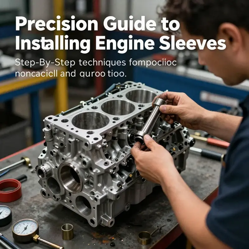
Installing engine sleeves is a specialized task that plays a critical role in restoring cylinder integrity or enhancing engine durability. Whether you own a motorcycle, a car, manage an auto parts distribution business, or run a repair garage, understanding the correct installation techniques ensures long-term performance and reliability. This guide outlines everything from foundational preparation to final verification, dividing the process into five detailed chapters that cover access and removal, installation with rubber/composite materials, the heating and fitment process for metal sleeves, and post-installation checks to confirm flawless results.
null
null
Accessing and Replacing Engine Sleeves: Safe Removal and Precise Installation
Accessing and removing worn or damaged engine sleeves is the turning point in any reliable engine rebuild. Whether you are replacing engine mounting bushings often called “sleeves” in repair contexts, or working with cylinder liners in a full re-sleeving job, the same principles of preparation, controlled access, and careful extraction apply. This chapter walks through a cohesive process that prepares you for a clean removal and sets the stage for an accurate installation, with attention to safety, fit, and long-term performance.
Begin by treating the vehicle and engine as a single system that must be stabilized. Park the vehicle on a level surface and make sure parking brakes are set. The engine must be cool to the touch. Disconnect the battery negative terminal to prevent accidental starts and avoid shorts when handling metal tools near electrical components. If you will be removing mounts or support brackets, plan to support the engine from below with a jack and a wooden block or use a professional engine support bar. Never rely on the mounts alone once bolts are loosened.
Next, create a clear work area and remove obstructing parts. Radiators, airboxes, intake plumbing, exhaust components, and ancillary brackets often block access to sleeves or bushings. Remove only what you need to free access, and tag hardware and small parts as you go. Digital photos of each step help when reassembling complex linkages. Keep fasteners organized by location. Clean the surrounding area with degreaser and rags. Dirt and grime can hide threads or damage mating surfaces during removal.
With the engine supported and access achieved, inspect the mount or sleeve and identify the fixing method. Many engine mounting bushings are held by a bracket and through-bolt assembly. Cylinder sleeves or liners may be press-fit, threaded, or bonded. Note whether the sleeve has a retaining collar, snap ring, or adhesive bead. This observation determines removal strategy. If there is corrosion or seized bolts, apply penetrating solvent and allow it time to work before applying force. Gentle heat can aid in loosening stubborn fasteners, but avoid excessive heat near rubber, plastic, or electronic components.
Loosen mounting bolts in a controlled sequence to avoid sudden shifts in engine position. Back bolts out a few turns first, then support the engine weight gradually as you remove the final fasteners. If you are removing an engine mount bushing, retain the bracket and any spacer sleeves so you can measure the original fit. For press-fit sleeves, use a proper sleeve puller or a hydraulic press when available. A puller with a spreader and a central forcing screw gives even pressure and minimizes damage. For smaller bushings, a slide hammer set with appropriate attachments can extract the sleeve without distorting the housing.
When a sleeve is bonded with adhesive, heat softening can be effective. Use a heat gun to warm the adhesive evenly. Do not overheat metal parts; heat can alter material properties. Apply heat gently around the perimeter until a hand tool can pry the sleeve free with minimal force. For internal liners or cylinder sleeves, consider a chemical adhesive softener recommended for the bond material. If a sleeve is rust-seized, carefully cut a relief groove in the outer body to break corrosion bonds. Use cold chisels or rotary tools with care, avoiding damage to the housing bore.
Always protect the mounting bore or engine bracket during extraction. Place split bushings, copper backing plates, or soft metal spacers between the puller jaws and the housing to distribute load. Avoid prying directly on thin metal brackets that can bend. If a housing distorts, the new sleeve will not seat correctly. For larger sleeves, consider removing the parent component (for example, the entire mount bracket or pedestal) to a workbench where a hydraulic press can be used. This often saves time and reduces the risk of damage to the vehicle.
Once the old sleeve is out, clean and inspect the housing thoroughly. Remove rust, paint flake, and old adhesive with a wire brush, abrasive pad, or fine emery cloth. Wipe the bore with solvent, then dry it completely. Measure the bore diameter and assess the roundness. If the bore is pitted or out of round, reconditioning may be required. Machining or reaming to restore concentricity is sometimes necessary. For engine mount housings, light rust and burrs can be dressed, but deeper corrosion may force replacement of the entire bracket.
Prepare the new sleeve with the same care. Confirm part numbers, compare the new sleeve to the original, and check for defects. Clean the sleeve’s outer surface and apply a thin film of manufacturer-recommended lubricant or anti-seize compound if specified. For rubber bushings, avoid petroleum-based lubricants that degrade elastomers. For metal sleeves, a light oil is usually acceptable. If the installation calls for a press fit, align the sleeve squarely with the bore and use a guide sleeve or drift to maintain concentric pressure.
Press the new sleeve in with steady, even force. A hydraulic press with the correct adapters yields the best control. Where a press is not available, a hand tool approach using a socket or pipe that bears on the sleeve’s outer face can be used. Tap gently with a rubber mallet and good alignment. The sleeve must enter straight; a single degree of tilt can cause binding. For metal liners that require thermal fitting, heat the sleeve to the prescribed temperature and cool the housing if recommended, then seat the sleeve quickly. Strictly follow temperature guidelines to avoid altering material properties.
After the sleeve is seated fully, inspect its orientation and position. Many sleeves have a stop or groove that must align with a housing feature. Verify that any snap rings are reinstalled correctly. Reassemble mounting brackets and torque all fasteners to the manufacturer’s specifications. Torque values matter; under-torquing allows movement and wear, while over-torquing can crush bushings or strip threads. Reconnect any removed components and ensure all connections are clean and secure.
Finally, perform a dynamic check. Start the engine and observe for abnormal vibration or movement. Test the vehicle at low speed to confirm noise and isolation characteristics are restored. After a short break-in period, re-inspect the sleeve and mount hardware. A follow-up check after a few hundred miles is wise, as initial settling can reveal loose bolts or misalignment. For more detailed guidance on removing sleeves from engine blocks, consult a practical resource on removal techniques to complement this workflow: “how to remove engine sleeves”.
This integrated approach — protect the engine, control access, use the right tools, and verify fit — greatly reduces the chance of error. Removing an old sleeve is not just about extraction; it is a diagnostic and preparatory step that sets the stage for a durable installation and dependable engine performance.
External resource: https://www.youtube.com/watch?v=QKJfRgYVz6w
Sleeve Installation Techniques for Rubber and Composite Engine Sleeves: Precision, Alignment, and Sealing
Installing rubber or composite engine sleeves is a precision-focused task that sits at the intersection of material science and mechanical fit. These sleeves are chosen for their damping properties, thermal insulation, and noise reduction, not for the brute-force strength that metal sleeves often rely on. Because of their flexible nature, rubber and composite sleeves demand careful handling, exact bore preparation, and a controlled insertion that avoids localized stresses. The goal is not merely to drop a sleeve into a hole but to achieve concentric seating, a clean seal, and a durable interface between sleeve and block that will perform under heat, pressure, and long service intervals. To understand the essence of sleeves and how they function within the block, consider reviewing a primer on engine sleeves to ground the discussion in the core concepts. What are engine sleeves?
Preparation begins long before the sleeve ever touches the bore. The work area must be clean, well-lit, and free of debris that could nick the sleeve’s surface or contaminate the sealing face. Compatibility is non-negotiable; the sleeve you select must match the engine model, bore size, and the intended operating conditions. A mismatch can create fit issues that ripple through the sealing system and put mating components at risk. Before any tool touches metal, inspect the sleeve for manufacturing defects—cracks, tears, or deformities can doom the install and shorten the sleeve’s life. The surrounding block bore should be checked for cleanliness and roundness. Any corrosion or outstanding residue can compromise concentric seating and the effectiveness of the elastomeric seal that the sleeve is supposed to rely on.
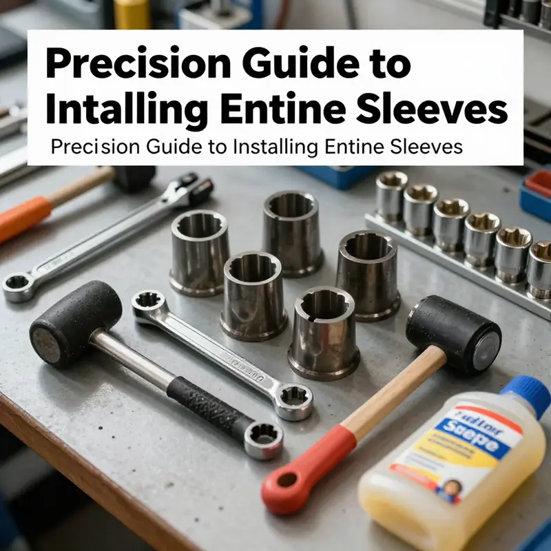
With the block prepared, the assembly team collects the required tools and consumables. A torque-controlled approach is essential, so a calibrated torque wrench is part of the kit, even though the installation of a rubber or composite sleeve relies more on uniform pressure than on precise bolt tightness. The assembly team may need a specialized installation tool designed to apply even circumferential pressure around the sleeve’s outer diameter. In the absence of a dedicated tool, a carefully chosen press-in method using a collar or an appropriately sized guide tube helps distribute force evenly. A floating or flexible interface jacket can prevent the sleeve from catching on the bore edge during insertion. Lubrication plays a pivotal role, but not all lubricants are appropriate. The sleeve’s material dictates what is permissible. In most cases, a silicone-based lubricant compatible with the sleeve material serves as a smooth insertion aid without compromising the elastomer or the seal. Excess lubricant is a trap for debris and can wash away critical seal surfaces during cranking and heat cycling. If the sleeve is intended to create a seal using an O-ring or elastomeric gasket, the O-ring surfaces must be clean, dry, and free of lubricants that could cause slip or bleed during operation.
The bore itself deserves particular attention. Cleaning is not a cosmetic step; it is a functional prerequisite. Any residue—oil film, old gasket material, rust scale—can disrupt seating and create a path for leakage. The bore should present a uniform surface with no nicks that could gouge the sleeve during insertion. If the block has any corrosion around the seating plane, it should be addressed through approved surface-prep methods recommended by the sleeve manufacturer. After cleaning, a quick concentricity check helps confirm that the bore’s axis aligns with the block’s axis, reducing the chance of cocking the sleeve as it enters. In high-precision contexts, a dial indicator or a slim, calibrated gauge is used to verify that the bore is within tolerance and true in multiple axial directions.
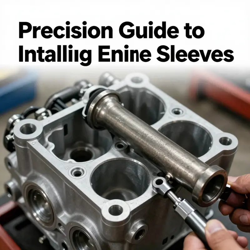
Insertion of rubber or composite sleeves hinges on controlled, even pressure and precise alignment. The first challenge is to align the sleeve with the bore’s axis so the seal forms a uniform ring and does not become pinched. A dedicated installation tool is ideal because it applies pressure uniformly around the circumference rather than concentrating force at a point, which could distort the sleeve. If a tool is not available, it’s possible to use a press with a circular collet or a home-built guide that centers the sleeve and provides a soft contact surface. The guiding device must be free of sharp edges and capable of distributing load evenly as the sleeve slides into place. During the approach to the final seating depth, the installer should monitor for any resistance that indicates misalignment or an obstruction at the bore edge. A light touch with a rubber mallet on a press-fit collar can help guide the sleeve into place, but all impact should be gentle and directed to avoid deforming the sleeve’s flexible material.
Lubrication, when used, should be applied sparingly to the sleeve’s outer surface and to the inner bore region that interfaces with the elastomeric seal. The chosen lubricant must be compatible with the sleeve material and not degrade the elastomer or compromise the seal. A common practice is to apply a thin film only where contact is expected, ensuring that the outer diameter slides smoothly into the bore without creating a film that traps contaminants or alters the interference fit in the seal zone. One of the most critical finishing points is the seal itself. The O-ring or elastomeric gasket forms a leak-proof barrier between sleeve and block. After seating, the seal surface must be inspected for damage, deformation, or twist. Any sign of twist or irregular seating should trigger a rework before the engine is run. The repair may involve re-cleaning, rechecking concentricity, or, in extreme cases, replacing the sleeve if misalignment cannot be corrected.
Concentricity checks remain a core part of the installation discipline. Once the sleeve is in position, the bore’s axis should align with the block’s axis. A dial indicator can confirm radial runout at critical cross-sections, ensuring there is no tilt that would put undue strain on the sleeve or its seal during thermal expansion. If the block design includes a press-fit portion that lightly grips the sleeve for a long-term assembly, confirm that the measured seating depth matches the specification. Any deviation could affect the seal’s effectiveness or introduce a thermal mismatch that compounds under engine heat. The installation manual from the sleeve manufacturer often specifies the required tolerances and seating depth; when in doubt, pertinence to those tolerances should guide decisions about whether to press further or withdraw and start anew.
After the sleeve is seated, the block should be prepared for final assembly in a way that preserves the sleeve’s integrity. The surrounding components that interface with the bore—head gaskets, ring land surfaces, and coolant channels—must be free of debris and correctly aligned. The next steps would typically involve reinstalling related components and torquing fasteners to the prescribed values, but with sleeves that rely on sealing with elastomeric elements rather than a permanent metal-to-metal press, the torque steps often serve to clamp and compress the interface rather than to affect the sleeve’s seating. The key is to ensure that the compression on the seal is even and that no part of the seal is exposed to a point load that would cause failure. A final visual inspection confirms that the sleeve sits fully recessed to the designed depth, the seal is uniformly seated, and the bore’s walls show no sign of scoring or damage.
What follows installation is a validation phase that blends static checks with functional tests. A leak test at a controlled engine condition helps verify the integrity of the seal and the sleeve’s seating under realistic loads. The test should be designed to reveal any path for leakage that a visual check might miss. If leakage is detected, return to the inspection stage, addressing any debris, misalignment, or damaged seal. A careful, measured approach reduces the risk of overcorrecting and creating new issues. As with any specialized process, it’s important to reference the manufacturer’s documentation for tolerance standards and methods, and to consult official engineering resources for application-specific guidance. In many cases, manufacturers publish technical manuals that detail how their sleeves should be installed, the tolerances to maintain, and the best practice sequence for seating and testing. These resources provide confidence that the process aligns with the engine’s expected thermal and mechanical behavior across operating conditions.
The broader relevance of the procedure lies in its emphasis on cleanliness, alignment, and controlled force. Rubber and composite sleeves do not tolerate rough handling or enjoys a generous margin for misfit. They require a mindset that treats the bore as a delicate interface and the sleeve as a component that must be coaxed into place without introducing micro-damage. The result—properly installed sleeves with reliable seals—translates into reduced vibration transmission, stable sealing, and a more predictable engine performance profile across temperature ranges. For anyone integrating sleeves into an engine rebuild, these principles help ensure that the investment in a rubber or composite sleeve pays off in durability and performance rather than early wear or leakage.
For readers seeking deeper theoretical grounding or model-specific instructions, consult official technical documentation that addresses tolerance standards and installation procedures. Such resources give actionable guidance that reflects real-world engineering constraints and the limits of material behavior under cycling temperatures and pressures. As a reminder of the knowledge foundation, consider the broader literature on sleeves and their applications in modern engines. The internet hosts a wealth of practitioner guidance, but the most reliable sources are the manufacturer manuals and technical documentation that accompany each sleeve design. External resources can enrich understanding of the principles at play and help align practice with verified standards. External reference: https://www.cummins.com/support/technical-resources/engineering-and-service-manuals.aspx
In sum, installing rubber or composite engine sleeves demands a blend of preparation, controlled seating, precise alignment, careful sealing, and rigorous verification. It is a procedure that rewards a meticulous approach and a commitment to maintaining the integrity of the bore and the sleeve’s elastomeric interface. The narrative of sleeve installation is not about a single clever trick; it is about a disciplined sequence that respects material behavior and engineering tolerances. When done correctly, the result is a well-sealed, dimensionally stable sleeve assembly that supports engine reliability over many miles of operation.
Precision Heating and Fitment: Installing Metal Cylinder Sleeves Correctly
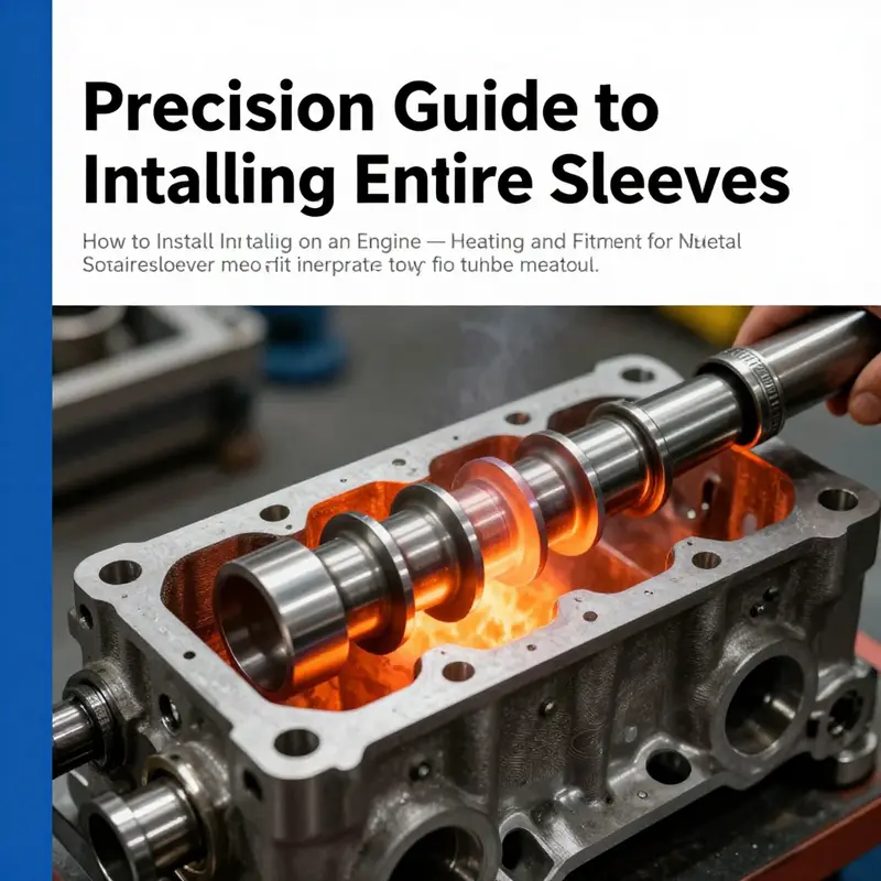
Precision Heating and Fitment: Installing Metal Cylinder Sleeves Correctly
Installing metal cylinder sleeves is a task that demands careful planning, controlled heat, precise measurement, and steady hands. Unlike simpler repairs, sleeving an engine alters the core geometry that pistons, rings, and valves rely on. The sleeve must sit true, at the correct depth, and with the proper interference fit so the finished bore is concentric and dimensionally stable. This chapter walks through the critical thermal and mechanical steps that make a sleeve installation reliable, describing why each choice matters and how to avoid common mistakes.
Start by confirming the sleeve type and the intended fit. Dry sleeves seat against the block material directly and depend on an interference fit to stay put. Wet sleeves are surrounded by coolant and rely on sealing surfaces and precise protrusion to maintain coolant integrity. The interference spec from the sleeve manufacturer is the guiding number: it determines how much interference the sleeve outer diameter will have with the prepared bore at ambient temperature. That interference is often achieved with a thermal differential — expanding the sleeve with heat or contracting the block bore slightly to allow insertion with controlled force.
Cleanliness and measurement come before any heating. Remove all oil, grime, and machining debris from both the sleeve and the block bore. Inspect the block for cracks, out-of-round sections, and deck warpage. Use a bore gauge and outside micrometer to confirm the sleeve outer diameter and the bore diameter. Record these numbers; they tell you the expected interference and guide the heating target. Also check the deck surface for flatness and perpendicularity to the bore axis. If the deck is warped, the sleeve may tilt during seating, creating misalignment that cannot be undone by re-machining later.
Select a heating method that gives repeatable, even expansion. Sleeve heaters with temperature controls or hot-oil baths are preferred because they distribute heat uniformly and are easy to monitor. An oven large enough for the sleeve works as well when temperature control is precise. Avoid open flames and uneven heating that can distort the sleeve. Typical heating brings the sleeve to a temperature that yields just enough radial expansion to overcome the interference — enough for insertion, but not so high that the material properties change. The exact temperature depends on sleeve material and interference amount; follow manufacturer guidance.
Decide whether to cool the block bore. In many professional shops, the block is stabilized at ambient or slightly warmed temperature while the sleeve is heated. In some cases, controlled cooling of the block or the use of dry ice on the bore can marginally increase the clearance window, but this adds complexity and risk of condensation. The simpler and safer method is to heat the sleeve to a predictable temperature and keep the block clean, dry, and supported.
Alignment during insertion is non-negotiable. Use a mandrel or alignment guide that fits through the sleeve and into the crank bore or main journals to hold concentricity. This guide prevents tilt and keeps the sleeve coaxial with the crank axis. A sleeve pressed in at an angle will create an eccentric bore that produces poor piston-ring sealing and accelerated wear. Position the block securely in a press or on a stable fixture so it cannot shift as the sleeve enters.
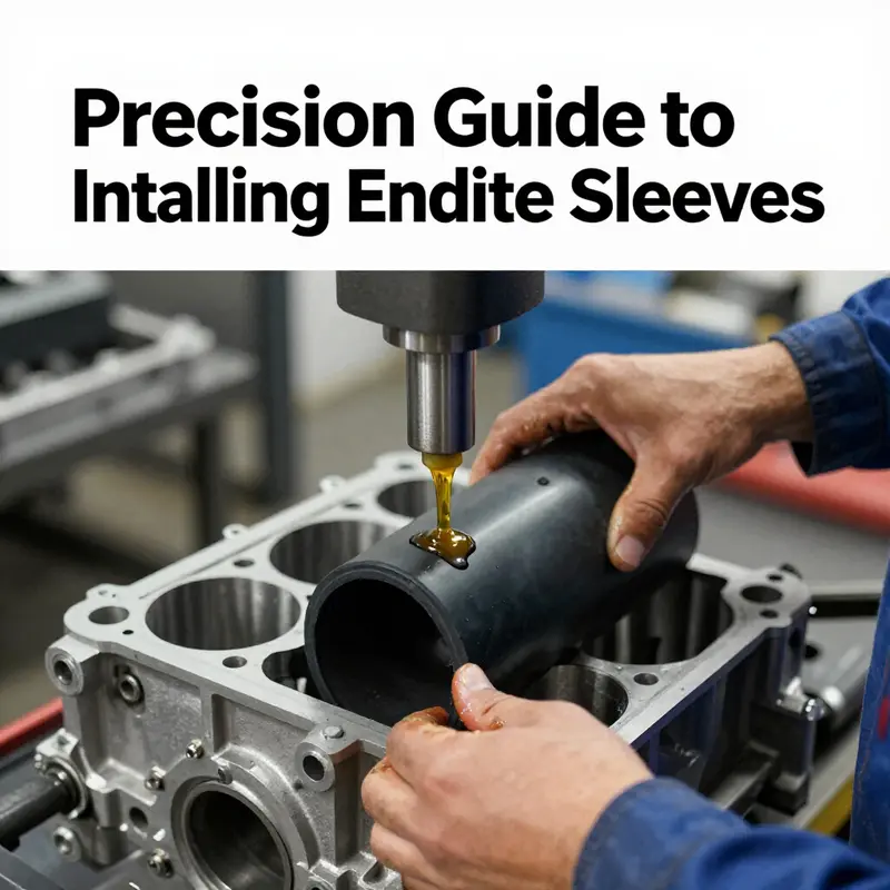
Lubrication must be chosen carefully. Some sleeve manufacturers allow a thin film of oil or specified lubricant on the outer diameter to ease insertion and prevent galling. Other manufacturers prohibit any lubricant, as it can alter the effective interference or contaminate sealing surfaces. Apply only the lubricant recommended and in the minimal amount required. Excess lubricant can allow the sleeve to move after seating or hide incomplete seating until the engine is in service.
Press the sleeve in smoothly and steadily. Use a hydraulic or mechanical press sized for the job. The force should be applied evenly across the sleeve flange or a backing plate to avoid deforming the sleeve mouth. If a drift is required, use a soft-faced installer to prevent scoring. Drive the sleeve at a controlled rate; rapid movement can produce impact stresses that distort the fit or crack the block. Monitor alignment throughout insertion with dial indicators or feeler checks against the alignment mandrel.
Seat the sleeve to the specified depth. Many sleeves have a seating shoulder or a predefined protrusion tolerance relative to the deck. Use a depth gauge or comparator to verify the sleeve is flush or protruding by the correct amount. Incorrect protrusion changes combustion chamber volume and can interfere with head gasket sealing. If the sleeve sits too deep or too shallow, remove it and re-seat with proper setup; minor trimming or machining of the block surface should be done only when within allowable repair methods.
After seating, allow the sleeve and block to return to ambient temperature under controlled conditions. Thermal contraction will lock the sleeve in place. Re-measure bore concentricity and protrusion after cooling. Even if measurements looked good during installation, final checks are essential because materials settle as they change temperature. If concentricity or seating depth is out of tolerance, identify the source: misalignment, block distortion, or incorrect heating. Address the cause rather than forcing corrective machining that masks an underlying error.
Final sizing of the inner bore occurs only after the sleeve is fully seated and verified. Boring, reaming, and honing remove minimal material to achieve final diameter and crosshatch finish. Use precision tooling that runs true in the installed sleeve. The final honing or finishing step produces the ring crosshatch that promotes oil control and ring seating. Avoid excessive material removal that reduces sleeve wall thickness below safe limits. Maintain concentricity by using tooling supported by the block deck or guides that match the sleeve axis.
For wet sleeves, verify sealing and coolant interfaces after the engine goes through a thermal cycle. Pressure-test coolant passages and check for leaks around the sleeve perimeter and any O-rings or gaskets used in the installation. Any sign of coolant ingress into oil passages or unexpected leakage is cause to remove and inspect the sleeve-seat surfaces.
Document the installation: record sleeve identification, outer and inner diameters, seating depth, heating temperature, and final bore size. This record helps future rebuilders and can indicate whether a deviation occurred. Most importantly, if you are not experienced with sleeve installation, consult a qualified machinist. The controlled use of heat, precision measurement, and alignment tools is the difference between a successful sleeve job and a costly engine failure.
For a broader overview of sleeve types and considerations, see this detailed explanation of engine sleeves: what are engine sleeves.
Cylinder Sleeves: Precision Fit and Verification
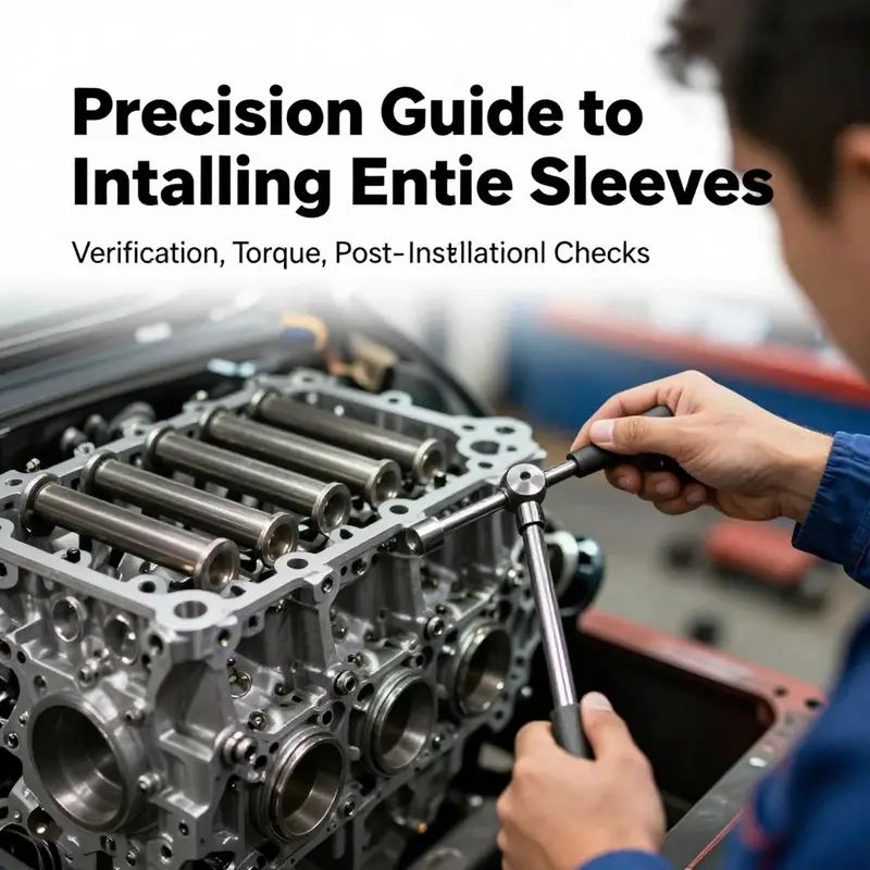
Sleeve installation is a precision operation that restores the engine core geometry. This chapter outlines a disciplined approach focused on preparation, correct sizing, controlled seating, reliable sealing, and verification before reassembly. The aim is a concentric bore, stable compression, and even oil and coolant flow across thermal cycles. Never force a sleeve into a bore. If the outer diameter or the bore diameter do not meet the engine makers tolerances, stop and recheck measurements or change to a different sleeve size. The process begins with thorough cleaning of the block and inspection of the bore surface. Use a bore gauge and a micrometer to measure bore diameter, sleeve outer diameter, and sleeve to bore clearance. Typical values fall in a narrow range and any reading outside tolerance should trigger corrective machining or a change in sleeve size. Preparation also includes selecting a suitable sleeve installation lubricant and the correct press tool to maintain true alignment during insertion. A guided sleeve press or a properly sized driver with a concentric mandrel is preferred for a clean seating. The sleeve edge should sit flush with the block surface within a small tolerance. The top land and any sealing grooves must be clean and free of debris before the sleeve is pressed into place. Sealing components such as lip seals or o rings are installed with care in their grooves, and a thin film of high temperature lubricant may be used in the grooves or recesses as specified by the manufacturer. During seating, advance the sleeve in small increments, pausing to verify vertical alignment and concentricity with the bore. If tilt is detected, remove the sleeve and correct the alignment before continuing. Once the sleeve is seated, verify the depth reference and inspect for even seating around the circumference. After seating, check the seal grooves for debris and confirm that seals are oriented toward the correct direction for the combustion environment. A light smear of the specified sealant or gasket lubricant may be applied to the recesses, but avoid excessive bead height that could be extruded into the combustion space. Verification steps include a pressure test of the cooling jacket and oil gallery to ensure there are no leaks after assembly. Use appropriate adapters and monitor pressure stability over several minutes. If a leak is detected, recheck seating depth, alignment, and groove integrity and repeat as needed. Reassembly should follow the engine maker specified torque sequence and torque values, using a torque angle method if required. Recheck all surrounding components and fasteners to ensure clean gaskets and proper sealing. After the engine is reassembled, perform a controlled run in. Bring the engine to normal operating temperature and monitor for unusual noises or temperature spikes. A cautious initial drive helps the new sleeves settle and promotes even bearing and oil flow. A typical break in may involve light to moderate loads for a defined distance as defined by the manufacturer. In summary, the key to reliable sleeve performance is strict adherence to measurement, proper seating, careful sealing, thorough verification, and controlled reassembly followed by a thoughtful break in. Always consult the official service documentation for the specific engine family to obtain the exact torque values, clearances, and procedures.
Final thoughts
Properly installing engine sleeves enhances the life and resilience of both motorcycle and auto engines. Attention to preparation, precise removal, correct press or heating methods, and thorough final checks ensures the sleeves function as intended—absorbing vibration, maintaining cylinder integrity, and supporting engine stability. By following these five chapters, professionals and enthusiasts alike can achieve a confident, long-lasting installation that safeguards engine performance.