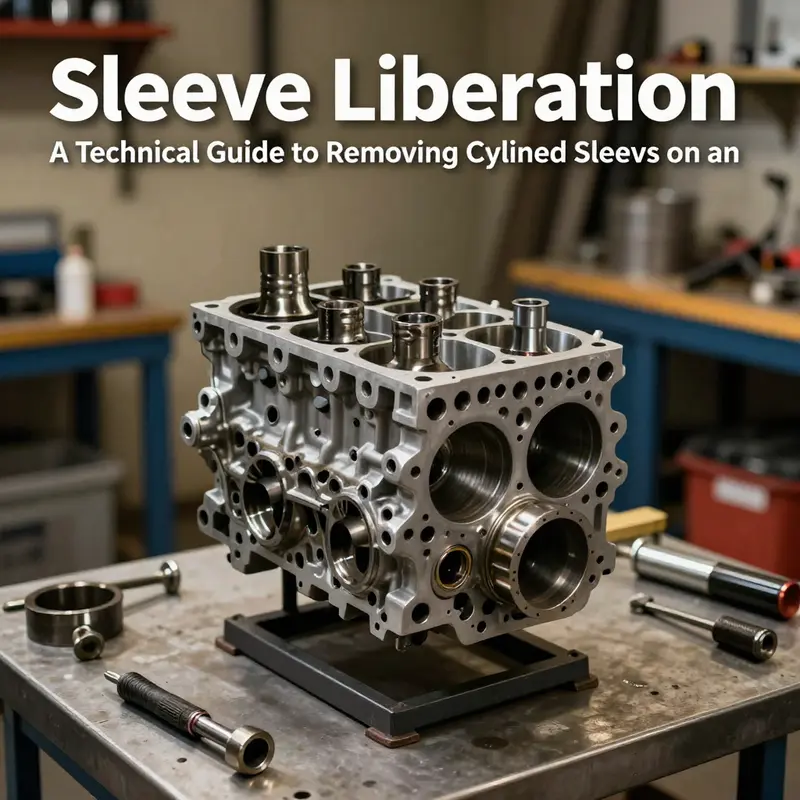
Cylinder sleeves (liners) are the critical interface between the combustion chamber and the engine block. For motorcycle riders, auto owners, auto parts distributors, and repair shops, knowing how to remove sleeves from an engine block is a practical skill when overhauls, bore restoration, or sleeve replacement becomes necessary. The process demands precision, clean environments, and the right tools to avoid compromising bore geometry or block integrity. This guide divides the task into three focused chapters: preparation, disassembly, and initial inspection; sleeve removal techniques with emphasis on alignment; and post-removal bore preparation and sleeve installation if replacement is required. By following controlled steps—careful measurement, proper tooling, and strict cleanliness—technicians and enthusiasts can prevent damage, ensure a true bore, and set up for a successful sleeve install. Whether you work in a repair shop, stock sleeves for distribution, or rebuild engines for customers, the core principles stay the same: plan, align, and verify before moving to the next phase.
Chapter 1: The Quiet Precision of Sleeve Removal—Preparation, Disassembly, and the First Look Inside the Engine Block
The act of removing engine sleeves is not a spectacle of brute force but a disciplined ritual of precision. It demands respect for the material, a calm mind, and access to the right choreography of tools. The sleeves—whether dry or wet, integral to the block or inserted as liners—are the interfaces between combustion pressure, cooling, and the piston’s travel. They carry the bore’s fate, and any misstep in their removal can cascade into warping, loss of alignment, or a crack that compromises the entire rebuilt heart of the machine. This chapter threads the reader through the earliest, most consequential phase of a sleeve replacement project: the careful preparation, the deliberate disassembly to reach the block, and the initial inspections that determine whether the block remains a solid foundation or must be reconditioned before new sleeves are pressed in.
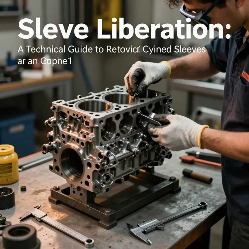
Preparation begins long before any wrench is turned. It starts with a mindset that blends respect for the engine’s engineering with a practical plan for safety and cleanliness. The engine should be cool, and the vehicle level on a stable surface. Electrical safety is not a formality but a foundation: disconnecting the negative battery terminal eliminates the risk of accidental shorts during work that robs power to critical sensors and grounds. The work often requires removing the engine from the vehicle to gain unfettered access to the block. A well-configured engine hoist, positioned on a solid shop floor, is as essential as any wrench. The process of removal is not a single event but a sequence of decisions: which components must come off in what order, how to protect cooling lines and oil passages, and how to preserve the integrity of gaskets and mating surfaces for reassembly. The goal throughout is to keep the engine in a state where reassembly can occur without surprises.
As the engine comes apart, a careful eye follows each part to its own temporary home: the cylinder head, intake and exhaust manifolds, timing components, and the oil pan. The disassembly phase is not merely mechanical; it is diagnostic. The block is exposed as a map of wear and potential trouble. The bore surface under the head gasket line is the first region to assess for scoring, glazing, or ringland contact that hints at heat stress or lubrication failure. The sleeve itself—dry or wet, integral or removable—will reveal its character in the farther reach of the bore and the collar that anchors a liner or seals a wet sleeve. The distinction between dry sleeves pressed into the block and wet sleeves integrated with coolant passages may seem technical at first glance, but it dictates the extraction strategy and the protection required to avoid collateral damage to coolant channels and sealing surfaces.
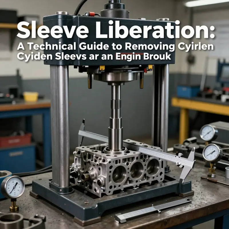
The choice of removal method is driven by sleeve type and the block’s geometry. When sleeves are dry and pressed into the bore, the common approach is the hydraulic press: a press applies uniform, controlled force to the sleeve’s outer diameter, coaxing it out without bending the bore or warping the block. Alignment is not optional but mandatory; a misaligned press can leave the bore scarred or the block wallowed. For sleeves with a flange or top lip, a specialized puller can sometimes extract the sleeve by grabbing the flange and pulling upward. This method is not universal; it depends on the sleeve’s design and the block’s construction. In stubborn cases, a measured application of heat around the sleeve area—using a heat gun or an induction heater—can yield a small expansion of the metal, easing removal. Caution governs heat because excessive warmth can alter the heat treatment of the block or draw distortion into the bore. The guiding principle is to apply just enough force or expansion to release the interference fit without compromising the material’s microstructure or the block’s structural integrity.
The act of disassembly goes beyond forcing sleeves out. It requires a disciplined approach to protect the bore’s surfaces and the block’s external walls. This is a phase where the machinist’s experience matters as much as the tools do. For many engines, the sleeves—whether dry or wet—conceal or reveal the next steps of restoration. Dry sleeves, once removed, leave a clean, precise bore ready for inspection and, if needed, new sleeves. Wet sleeves leave cooling passages exposed, and their removal must respect the seals that keep coolant from mixing with the oil and from leaking into combustion chambers. The disassembly phase also offers the moment to inspect ancillary features: the alignment of the main bearing caps, the straightness of the bore axis, and the presence of any cracks radiating from the cylinder walls. The presence of cracks, even tiny ones at the edge of a bore, can be a harbinger of more serious block deformation. The strategy then shifts from removal to evaluation: does the bore require honing or boring prior to sleeve installation? Is the block a candidate for reconditioning, or has it reached a point where replacement is prudent? The questions are not abstract; they define the financial and mechanical viability of the rebuild.
The practical sequence of steps, while seemingly linear, culminates in a more holistic approach to the engine’s future performance. After the cylinder head is removed in accordance with the manufacturer’s torque sequence, the technician identifies the sleeve type and the correct extraction method. Dry sleeves are typically removed with a sleeve puller designed to engage a flange or scuffer on the sleeve; the puller applies a steady upward force, and the bore’s wall remains unscathed only when the force is evenly distributed and the alignment is true. Wet sleeves, by contrast, require careful disengagement of the seals from the sleeve grooves. The coolant passages must be respected during removal to prevent stray coolant from entering the oil or combustion spaces during future reassembly. In both cases, the removal is not the end of a lesson but the beginning of a verification: once the sleeve is free, the bore must be clean, and a fresh inspection must confirm that material around the bore remains homogeneous, free of cracks, and within tolerance.
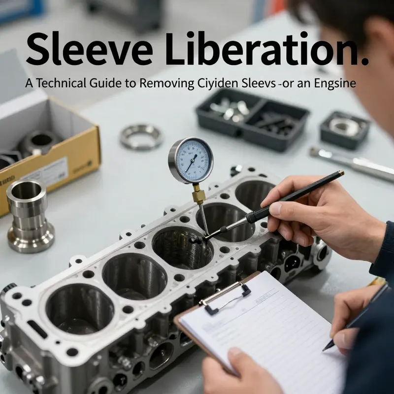
If the sleeves come out without incident, the next moment belongs to the bore. A clean bore is the stage on which the rest of the project will be built. Solvents, brushes, and lint-free rags are used to remove oil film, gasket residue, and minor corrosion. The bore’s surface must be inspected with a professional eye and precise tools. A bore gauge measures roundness and straightness, and a micrometer confirms diameter. The goal is a bore that is perfectly smooth, straight, and true to the engine’s specifications. Any irregularity—out-of-roundness, taper, or a bulge—calls for reconditioning. The decision may be to hone for a light, uniform surface or, in more severe cases, to bore for a larger diameter and install oversize sleeves. The hinge in the decision is the block’s structural integrity. A crack in the block, even if hidden, can render a budding rebuild untrustworthy. The disassembly and inspection phase, then, becomes a measure of the block’s capacity to serve as a robust platform for the new sleeves and the entire rebuilt assembly.
Within this narrative, a single, practical note anchors the chapter to the reader’s path forward. The exact method used to remove sleeves should be guided by the engine’s model and sleeve design, and while general principles apply, every application carries its own nuances. Readers who want a concrete workflow for the sleeve removal technique can refer to established procedures such as how-to-remove-engine-sleeves. That reference, while not a substitute for the manufacturer’s service manual, offers a concise reminder of the core principles: identify the sleeve type early, choose a removal method that respects the block’s geometry, and execute with controlled force and careful alignment to protect the bore.
The quiet precision of sleeve removal is as much about restraint as it is about technique. It demands the right tools, but it demands more the right judgment: when to press, when to pull, when to heat, and when to pause and re-evaluate the block. It requires cleanliness. It requires documentation—recording bore diameters, noting any scoring or surface defects, and mapping the block’s condition for the next phase. This isn’t about a single finish line; it is about establishing a solid foundation for the sleeve installation that will come next. The block must emerge from the process as a pristine stage for the next act—honing, sizing, and the precise seating of new sleeves to restore concentricity and sealing integrity. The engine, as a system, is rebuilt not by a single dramatic maneuver but by a chain of disciplined, repeatable actions that keep tolerances in check and wear patterns predictable.
In the broader arc of an engine rebuild, the preparation, disassembly, and initial inspection are the most vulnerable moment for the block’s long-term performance if rushed or mishandled. This phase teaches respect for the sleeve’s role as not just a sleeve but a critical interface that must be correctly prepared for the next stage. The sleeves’ removal is a gateway, not an ending: it opens the path to reconditioning or replacement, to careful measurement, and to the secure seating of new sleeves that will endure the pressures and heats of countless combustion cycles. The best outcomes arise when the team balances the art of manual technique with the science of metrology, recognizing that a measured approach to every turn of the wrench is what ultimately preserves the engine’s integrity after the sleeves are replaced and the block is readied for its final assembly. As the chapter closes on this preparatory phase, the reader understands that the next steps—installing new sleeves, honing the bore, and reassembling the engine—will test the same principles in new forms, requiring the same discipline, precision, and attention to detail that defined the sleeve removal itself. The surface that will soon carry a fresh sleeve rests now on a foundation of meticulous inspection and careful preparation, and it is this foundation that will determine whether the rebuilt engine will perform reliably and endure.
Precision Sleeve Extraction: Techniques, Alignment, and the Subtle Art of Removing Engine Block Sleeves
Cylinder sleeves are more than just a lining inside an engine block; they are the interface that governs heat flow, piston sealing, and long-term durability under high speeds and pressures. When an engine is rebuilt, sleeves may be removed to repair bore damage, to install new liners with a different interference fit, or to accommodate a bore re clearance after machining. The act of removing a sleeve is not a crude pull or an overzealous hammer strike; it is a carefully orchestrated operation that demands respect for the block’s geometry and metallurgical history. The danger of a careless approach is not only a scratched bore or a nicked piston crown but a distorted block that can compromise sealing surfaces, oil control, and ultimately engine reliability. In this chapter, we trace the path from preparation to reassembly, emphasizing how the choice of method, the control of forces, and the management of heat all converge to determine whether a sleeve is removed cleanly and whether the block is ready to accept a new sleeve with the precision demanded by modern engines.
The sleeves themselves occupy a pivotal role in both gasoline and diesel engines. They shield the block’s bore from wear, keep heat transfer predictable, and provide a stable, repeatable surface for the piston rings to seal against. When a sleeve is installed, it creates a precise, hardened interface that can withstand the normal friction and micro-welding that occurs between the piston rings and the bore during operation. But sleeves can also become a constraint: corrosion, poor initial fit, or bore distortion from overheating or improper assembly can necessitate their removal. The decision to remove a sleeve is rarely driven by a single defect; it is the culmination of a chain of observations and measurements made during teardown, inspection, and tolerance checks. And while the general concept of removal may seem straightforward, the execution demands a disciplined approach to avoid compromising the structural integrity of the block or the subsequent fit of a new sleeve.
Among the practical removal techniques, the pull-out method using a sleeve puller stands out as the most common and controllable when dealing with dry liners that sit firmly in the block. The hydraulic sleeve puller, when correctly matched to the sleeve’s outer diameter and to the bore geometry, enables a smooth, evenly distributed extraction force. The critical advantage here is control: even force reduces the risk of bore deformation, which is the real enemy of a successful rebuild. The tool uses a set of adaptive jaws or sleeves that engage the sleeve’s top edge or flange with a balanced grip. The operator applies steady hydraulic pressure, watching the sleeve’s movement and listening for any resistance that might indicate corrosion, a press fit that is not fully seated, or a bore that has become slightly oval. In cases where the sleeve has a small top flange, a puller with a dedicated top-grip insert can be more effective than a standard puller because it reduces the chance of tilting and ensures the force remains coaxial with the sleeve’s axis. The effectiveness of the pull-out method rests not only on the tool but also on the preparation that precedes it. Piston decks, rods, and the crank must be removed or secured to prevent interference, and the block should be supported in a way that keeps it perfectly level throughout the operation. The careful removal of the head, timing gear, and associated components creates a window of opportunity for precise engagement with the sleeve while avoiding misalignment that could ripple into the bore when the sleeve finally breaks free.
The process, however, is not exclusive to hydraulic pullers. Manual pullers remain invaluable in field settings or smaller shops where a hydraulic setup is not readily available. A manual puller, with a center screw mechanism, can still deliver controlled force if matched with appropriately sized jaws and a good seating surface on the sleeve’s lip. The key with any puller, manual or hydraulic, is to ensure the tool’s contact surfaces are clean and burr-free, to verify that the puller is centered on the sleeve, and to work gradually rather than applying a single, high-load impulse. A misaligned puller can apply eccentric force, risking bore scoring or, worse, a subtle distortion that alters the concentricity of the bore. In addition to pullers, some sleeves feature a flange or lip at the top that can be engaged by an adjustable jaw or a specialized sleeve extractor designed to grip the flange without intruding into the bore itself. The takeaway is simple: the removal should be performed with a tool that matches the sleeve’s geometry and the block’s design, with alignment as the highest priority.
When pull-out is insufficient due to rust, corrosion, or especially tight engagement, a press-out method can be employed. This technique uses a hydraulic or arbor press to push the sleeve out from the bottom of the block. The press-out approach requires rigorous alignment and a well-designed support fixture to prevent lateral movement. The block must be cradled securely, with the sleeve’s axis perfectly aligned with the press ram. Any deviation in alignment, even a fraction of a degree, injects a risk of bending or cracking the bore; and the consequence could be a block that must be discarded or an expensive repair that undermines the rebuild’s economic viability. A forming fixture or a sleeve-removal adapter can help distribute load and keep the block stable during the push. In practice, the press-out method is most effective in combinations where the sleeve’s interference fit is uniform across the bore and the bottom surface provides a reliable reaction point for the press to push against. Precision, in this context, means not only how much force is applied but where that force is applied and how evenly it travels through the workpiece.
Temperature is another lever in the sleeve removal toolbox. The heating method is used selectively when other methods stall or when the sleeve is tightly bonded due to long service or heavy corrosion. The concept is straightforward: heating expands the sleeve more than the surrounding block, reducing interference and allowing the sleeve to be teased free. The cooking must be controlled and uniform. A heat source such as an induction heater or a carefully controlled heat gun can raise the sleeve area to a carefully monitored temperature. The target range is modest, typically sufficient to expand the sleeve relative to the block without pushing the metal beyond the thermal limits of the block material. For most cast iron blocks, a surface temperature increase is enough to loosen the fit, but heat must be applied evenly around the circumference to prevent hot spots that could warp the bore. For aluminum blocks, the risk of heat-induced distortion is higher, and measured, conservative heating is essential. The operator must continuously monitor the heat with infrared thermography or contact probes to ensure the temperature stays within safe margins and to detect any asymmetry in heating that could indicate a nonuniform bond or hotspot.
The decision to heat, pull, or press is not a mere preference; it reflects the sleeve’s design, the block material, and the service history. The operator weighs the sleeve’s diameter, the height of engagement, and the presence of any bore coatings or corrosion that could complicate removal. Before any method is attempted, the block is stripped to bare surfaces and the bore is thoroughly inspected. Any cutting or grinding marks from prior work must be considered because they can create stress risers during removal. The surface finish around the bore should be flat and free of nicks to ensure a clean fit for the upcoming replacement sleeve. In all cases, the sequence of steps matters: verify that the pistons, rods, and head components are removed, protect the cylinder bores from debris and oil splash, and ensure that the block is uncluttered enough to allow a full range of tool movement. A cautious person can achieve more predictable results than someone chasing speed.
The larger picture is about alignment and measurement. Removing a sleeve is not about extracting material; it is about preserving the integrity of the bore so that a new sleeve can be installed with a precise interference fit. This requires meticulous measurement at several stages: rough bore size, the inner diameter of the sleeve, and the final bore roundness after removal. Dimensional control is fundamental because even a slight deviation can translate into a nonuniform compression of the piston rings, leading to reduced compression and higher oil consumption. The bore’s roundness and straightness must be within a few micrometers of tolerance for a high-performance rebuild, and the clearance between the sleeve and the bore must be calculated to achieve reliable, repeatable results with the replacement sleeve. It is here that the role of alignment tools becomes clear. A bore gauge checks the bore at multiple diameters along the cylinder axis, while a precision mandrel or alignment pins help keep components coaxial during insertion. The reinstallation phase, whether the sleeve is press-fit or slip-fit, hinges on the same principles of concentricity and surface finish. If the new sleeve is not aligned perfectly with the bore, piston rings can rub and generate undesirable wear patterns. Consequently, the reassembly process demands equal discipline, with the same attention paid to cleanliness, lubrication, and controlled force as during removal.
External considerations also shape the approach. The torque history of the engine, the presence of hard coatings or nitriding in the sleeve area, and the potential for micro-cracking in the block all inform the choice of method. The machinist’s experience becomes a kind of intuition: when to rely on a heat-assisted loosening, when to lean on a hydraulic puller’s smooth action, and when to introduce a press to avoid keluarga of lateral movement. It is this blend of technique, experience, and precise measuring that distinguishes a successful sleeve removal from a misstep that could compromise a block’s life. For practitioners seeking specific, hands-on instruction, a practical walkthrough exists as a companion resource. See the guide titled How to Remove Engine Sleeves for a detailed, step-by-step workflow that aligns with the principles described here.
In all cases, the core message is consistent: sleeve removal is a precision operation. It demands the right tool for the job, careful preparation, and a disciplined approach to force, heat, and alignment. The goal is not only to extract a sleeve but to do so without distorting the bore, scarifying the block surface, or introducing residual stresses that could propagate into future failures. The success of a rebuild hinges on preserving the block’s integrity. The sleeves, once removed, must be handled with equal care as they are replaced. A clean bore, exact concentricity, and appropriately matched interference-fit sleeves set the stage for reliable performance and long-term durability. As a closing thought, remember that this is less about brute force and more about engineering judgment and precision execution. The sleeve removal task, properly executed, is a quiet testament to the craftsmanship behind modern engine restoration.
Internal resource for practical guidance: How to Remove Engine Sleeves. This link provides a hands-on, model-agnostic walkthrough that complements the concepts discussed here and helps bridge theory with the actual steps technicians perform in the shop.
External reference that informs the industry-standard approach to sleeve removal, including the utility of hydraulic pullers and the importance of controlled force: https://www.toolsources.com/hydraulic-cylinder-sleeve-puller
After the Sleeves Come Out: Post-Removal Assessment, Exact Bore Preparation, and Delicate Sleeve Installation if Replacement Is Needed
When the sleeves finally give way and slide from their seats, the engine block reveals its true condition in a way the bores never did while the engine was running. The moment is both a relief and a turning point: relief that the obstruction has been removed and the opportunity to restore true cylindrical form, and a turning point because the next steps determine whether the rebuild will endure. The post-removal phase is not a mere checkbox exercise. It is a careful, methodical appraisal that blends precision measuring, material sensitivity, and a plan that respects the block’s geometry as it was cast or machined. It is here that the quality of the entire rebuild often hinges, because any undetected flaw or misalignment becomes a fault line in later performance. To approach this with discipline is to recognize that the bore is not simply a hole; it is a feature that governs compression, lubrication, heat transfer, and oil sealing. In this sense, the post-removal chapter is not a detour but a continuation of the same craft you began when the sleeves were first pressed in or cast as part of the block. A practical mindset leads the way: measure with intention, deburr and clean with care, and reserve the option of machining only for good reason and to exact specifications.
The first priority after sleeve removal is to confirm bore integrity. Even if the sleeve came out cleanly, the bore underneath can reveal hidden fatigue, micro-cracks, or distortion from heat cycles and prior interference. Begin with a clean workspace and thoroughly wipe the bore area. Dirt and debris can obscure flaws or, worse, cause scoring as you inspect or handle delicate measuring tools. The goal is to ascertain that the bore’s axis remains true to the crankshaft’s line of rotation and that the bore’s surface is smooth and uniform from top to bottom. A combination of measurement techniques provides the most reliable picture. Use a calibrated micrometer to take three vertical diameter readings at the top, middle, and bottom of the bore. Record these measurements as a baseline reference. Then employ a dial bore gauge to check for roundness and straightness by tracing the bore and confirming that the measured diameters remain consistent around the circumference. The differences you observe are not merely numeric curiosities. Even a few thousandths of an inch out of round or a taper from the top to the bottom can translate into noisy piston motion, uneven lubrication, and premature wear once a new sleeve is installed.
Beyond the quantitative checks, perform a visual and tactile assessment. Look for hairline cracks or chatter marks along the bore walls, signs of corrosion, or any discoloration that hints at overheating. These cues can indicate prior overheating, improper cooling, or micro-movements that occurred around the sleeve during service. It is essential to sense not just what the bore shows but what it implies about the block’s internal history. If any serious irregularities surface, the block may require additional machining or, in some cases, a replacement block. While the temptation to proceed quickly can be strong, a hasty decision here can compound problems later. The engine is a system; one compromised bore can undermine the whole rebuild.
Cleaning and surface preparation follow the inspection. The bore must be free of carbon, rust, old sealant, and any residue from the sleeve removal process. This step is more than cosmetic. Residual contaminants can distort measurements, cause seating surfaces to wear unevenly, or hinder a proper seal when a new sleeve is installed. A solvent wash followed by a careful brushing with non-metallic tools is typically sufficient, but avoid aggressive abrasives that could alter the bore surface. While cleaning, inspect the top and bottom edges of the bore for any burrs or sharp transitions. Deburring these areas prevents sleeves from catching on entry or protruding or seating incorrectly. Each edge should be smooth and radiused where appropriate, with care taken not to alter the bore diameter.
With a clean slate, you can decide on the sleeve path. If the plan is to reuse the original bore with a new sleeve, you must determine whether the bore’s size falls within the acceptable range for a standard, oversize, or undersize sleeve. The choice depends on the engine’s design tolerances and the sleeve’s outer diameter. In most common scenarios, the bore is honed or bored to achieve the final dimension that matches the selected sleeve’s outer diameter and interference fit. This is where the distinction between a sound rebuild and a marginal one becomes evident. If the bore shows any sign of out-of-roundness or taper beyond the manufacturer’s specifications, machining to a precise oversize may be required. This step should never be guessed; it must follow a verified specification from the engine’s service manual or a reputable machinist’s blueprint. The goal is to produce a bore that is perfectly round, concentric with the crank axis, and with a surface finish that supports a uniform, interference-fit sleeve.
Even when the bore looks good, the evidence of prior sleeve removal can influence what happens next. The seat in the block where the sleeve will reside must be symmetrical and free of damage. If the seat shows scoring or galling, it will not provide a stable foundation for the sleeve and can cause leaks or misalignment. The lack of a proper seat depth is another critical detail. A sleeve that is installed too shallow or too deep will not seal correctly against the head gaskets or the block’s deck. The protrusion of the sleeve above the deck surface is a parameter that must be controlled with high precision. The specifications vary by engine design, but in almost all cases the protrusion tolerance is tight, often within a few thousandths of an inch. Achieving the correct depth is a matter of careful measurement with your depth gauges and the right installation tooling. When the bore and seat are confirmed to be within spec, you can move forward with confidence toward sleeve installation, if you are replacing sleeves.
The installation phase demands equal parts patience and accuracy. If a sleeve replacement is planned, lubrication becomes a critical factor. A high-temperature assembly lubricant is applied to the outer surface of the sleeve to facilitate installation and to reduce friction that could mar the bore as the sleeve is driven into place. It is not enough to dip the sleeve in anything slick; the lubricant must tolerate the engine’s operating temperatures and remain stable during the press-fit process. Alignment is another non-negotiable. The sleeve must drop into the bore with its orientation features aligned to the block’s internal geometry. Some sleeves have keyways or alignment marks, while others rely on the press fit to seat them squarely. For sleeves without explicit alignment features, the machinist must rely on precise tooling and careful observation to ensure the sleeve’s axis lines up with the bore and crank axis.
Installing a sleeve, when replacement is required, is typically a press-fit operation. A hydraulic press applies even, controlled force to seat the sleeve without hammering or wincing the block. The process should be slow, with the operator watching for any shift in alignment as pressure is applied. Direct pressure on the sleeve must be avoided; instead, a mandrel or a soft-faced driver should bear on the sleeve’s outer diameter in a manner that prevents indentations or local hotspots of stress. The depth of the sleeve’s seating is checked continuously. The goal is to reach the exact depth specified by the engine’s design; most sleeves are intended to protrude a precise amount above the deck, so the top surface can be machined or finished to prepare for the head gasket and head mounting surfaces. After seating, another round of measurement confirms the coaxial relationship between the sleeve, bore, and crank axis. Even minor deviations at this stage can ripple into oil leaks or coolant passages misalignment.
Lubrication, alignment, and engagement are not the only concerns. The bore’s surface finish is a common influence on sleeve performance. A good surface finish on the bore that matches the sleeve’s outer finish reduces the chance of scoring during first startup and helps to achieve a seal without excessive torque or heat. If the engine uses dry sleeves, the statistical tolerance for finish may be slightly different than for wet sleeves, but the guiding principle remains the same: the bore must be smooth, straight, and free of defects, and the sleeve must seat securely with the proper interference fit. The joint between sleeve and block is both a mechanical and a thermal interface, so the surface finish and seating depth are not trivial. They are central to oil control, ring seal, and long-term durability.
A faithful rebuild includes meticulous documentation. Record the bore measurements at multiple stages, the sleeve’s outer diameter and depth, and the final protrusion. These records do more than satisfy a quality check; they provide traceability in case a question arises about tolerances after reassembly. It is also wise to label each sleeve with its intended position and to annotate any deviations discovered during inspection. This practice simplifies reassembly and reduces the risk of errors when you reinstall pistons, rings, and other components later in the rebuild. A well-documented process strengthens the rebuild’s integrity and supports future maintenance needs.
As you near the end of the bore preparation and potential sleeve installation, consider the broader roadmap of the rebuild. The block must be ready to receive the rest of the assembly: cylinder heads, pistons, rods, crankshaft, oil passages, coolant channels, and seals. All these systems depend on the bore’s precise dimensions and alignment. If you chose to replace sleeves, you will have new critical interfaces to monitor during subsequent teardown and reassembly—interfaces that determine oil retention, coolant sealing, and proper compression. If you elected to leave the original bore in place and simply refresh the surface with honed texture, follow the honing process with appropriate cleaning and inspection, and verify that the finished bore meets all the nominal parameters. In either scenario, the guiding principle remains the same: a bore that is true, a sleeve that seats cleanly, and a joint that seals without forcing the engine into compromised behavior.
The path from sleeve removal to final assembly is intimately tied to the choices you made early in the process. The decision to replace or not replace sleeves should rest on the bore’s condition after removal, the engine’s history, and the rebuild’s intended longevity. If you decide to proceed with replacement, remember that the installation is the moment when a chain of precise tolerances becomes a living, reliable engine. If you choose to reuse and refresh the bore, you must be equally attentive to the finish and seating, since the same precision governs long-term success. Either path benefits from a disciplined approach: measure, verify, and document; align, fit, and secure; then recheck. The end state—a properly seated sleeve with a bore that’s true to form—lays the groundwork for the next stages of reassembly and, ultimately, for dependable engine performance.
For readers seeking a practical, model-spanning reference to the sleeve removal and installation sequence, consider the detailed guidance available in community and professional resources. A widely used formulation for the removal phase and its limitations can be found in discussions that emphasize both the mechanical and the metrological dimensions of the task. In this broader context, the chapter you’ve navigated becomes part of a coherent continuum: from the initial disassembly through the post-removal assessment to the sensitive act of installing a new sleeve and restoring the block’s integrity. If you want to explore a dedicated, model-specific procedure that maps directly to the engine you’re rebuilding, a tailored checklist can be generated to fit your year, make, model, and sleeve type. This level of customization helps ensure that no critical clearance or seating parameter is overlooked in the rush to reassemble.
From here, the next section of the guide can broaden the scope to model-specific tolerances and the final reassembly steps, ensuring that the bore’s geometry and the sleeve’s fit stay within the design’s intended envelope while the engine’s life cycle begins anew. When you revisit the concept of sleeve removal in the future, you can carry with you the awareness that the process is not about extracting a simple part. It is about maintaining and restoring a surface that is central to the engine’s ability to convert heat into motion with reliability and efficiency. In that sense, post-removal work is just as essential as the initial sleeve removal itself, and it deserves the same careful attention and disciplined technique.
Internal link reference for further practical context: how to remove engine sleeves. This resource helps anchor the removal phase in a broader discussion of sleeve handling, while the present chapter focuses on what comes after and how to prepare the bore for a successful installation if you decide to replace.
External resource for deeper technical background: https://en.wikipedia.org/wiki/Cylinder_sleeve
Final thoughts
Successfully removing sleeves from an engine block hinges on disciplined preparation, controlled extraction, and meticulous bore readiness. By following the three-chapter workflow—start with solid prep and inspection, execute sleeve removal with proper alignment, and finish with thorough bore verification and installation planning—shops and DIYers can minimize block damage and ensure reliable sleeve fitment. The payoff is a true, clean bore that supports a new liner and long-term engine reliability.